GB
General notice (liability): the details of this technical documents serve for description. Consents regarding the availability of certain features or
regarding a certain purpose always require a special written agreement.
Page 23 GB 9.3 Right reserved to make technical changes!
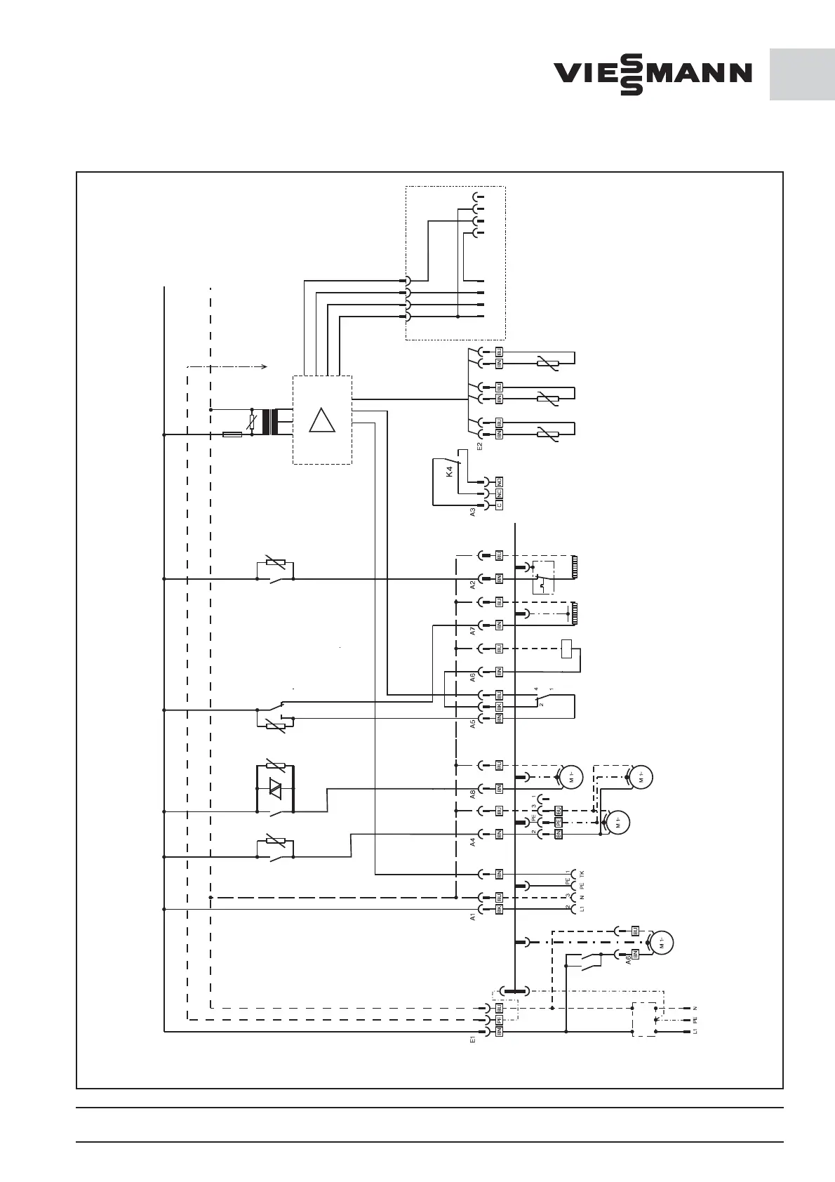
9.3 Electrical circuit diagram for
CT 3000 and FT 1500
2
2
RxD RxDSG SG
TxD TxD+12V
3
3
5
5
9
F2
80mA Tr
R1
K3
K1
K2 K5
R9
R8
R11
R10
KM
KM
E6
79
A1
A2
46
GND
RF VD VF
PE-Profile
Netfilter
Power supply plug
Compressor
4 -pin plug for
coldroom
Evapotator fan
Evaporatorfanr 2
for housing size 2
Condenser fan
Pressostat
Compressor
Oil heater
Defrost heating
External fault in dicator
(in cas e of fault or if
without power
relay is released)
Room sensor
Evaporator
sensor
Temperature sensors
PT 1000
Condenser sensor
(optional)
Connecting schematics for the optional
serial in terface RS 232 ,
included in systems supplied with
remote control