GB
General notice (liability): the details of this technical documents serve for description. Consents regarding the availability of certain features or
regarding a certain purpose always require a special written agreement.
Right reserved to make technical changes!Page 50 GB
7. Cooling mode
7.1 How the cooling mode works
After switching on the unit (Standby => No; see Point 8
‘First steps’), the cooling mode activates. If the unit was
only recently connected to the mains, the compressor
standstill time (usually three minutes) passes. The com-
pressor then switches on and starts the cooling process.
The condenser fan switches on at an appropriate speed
depending on the temperature at the condenser outlet.
On reaching the ‘Start evaporator fan’ temperature or
upon expiry of the ‘evaporator fan delay’, the evaporator
fan switches on. Depending on the humidity setting, the
fan runs at all times or when the compressor is switched
on (see parameter list in Point 9.3). The compressor runs
until the switch-off point is reached and re-activates
when the temperature increases to the switch-on point.
The points are determined by the desired coldroom
temperature and the hysteresis (see parameter list in
Point 9.3).
7.2 Description of the cooling mode types
Normal mode
The unit is started with ‘Standby = No’ then runs conti-
nuously. The cooling mode is only briefly interrupted by
the set defrost cycles.
Cooling schedule
The unit is started with ‘Standby = No’ then only runs at
the times approved in the cooling schedule. The cooling
mode is only briefly interrupted by the set defrost cycles.
The cooling schedule must always be programmed for a
week.
Emergency mode
The emergency switch on the unit’s motherboard
(see circuit diagram) has been activated. The unit runs
without interruption and temperature regulation. The
compressor and both fans run at maximum power. The
information ‘Emergency mode’ appears on the display.
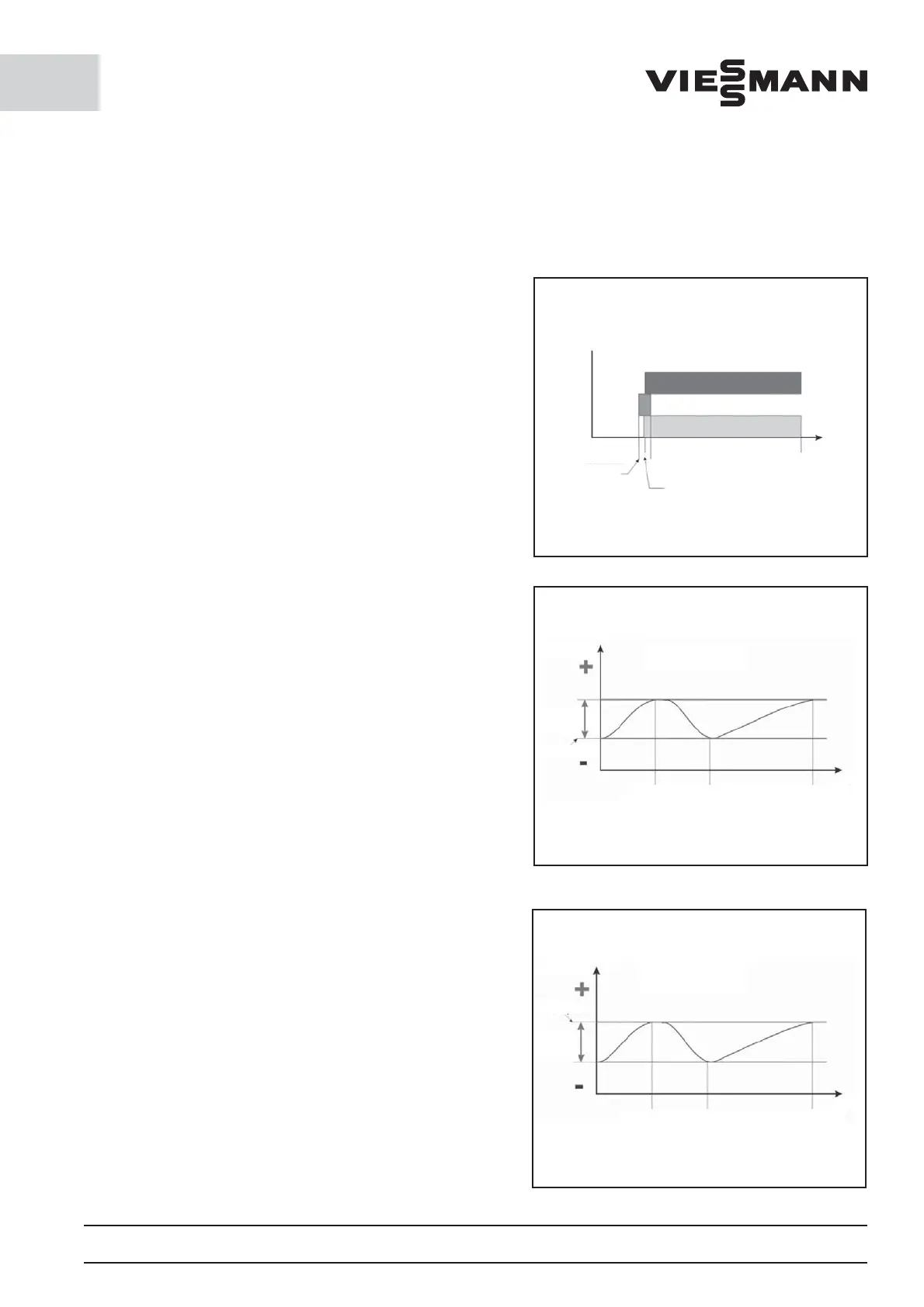
Relay
Compressor
Solenoid
valve
Bypass
Solenoid
valve
Fluid line
Temperature
monitoring by
ambient air sensor
Minimum
standstill time
Compressor must
have nished
Lead time
Bypass valve (sec)
Cooling running
Switch-o by
ambient air sensor
Time
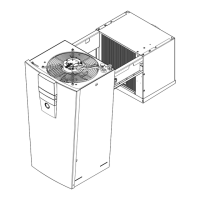
Cooling range
Temperature
Hysteresis
(2 to 8 K)
Target
temperature
Compressor
on
Compressor
o
Time
Compressor
on
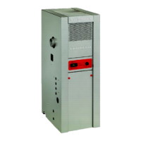
Temperature
Target
temperature
Hysteresis
(-2 to 8 K)
Compressor
on
Compressor
o
Time
Compressor
on
Deep-freeze range






 To Next Page