GB
General notice (liability): the details of this technical documents serve for description. Consents regarding the availability of certain features or
regarding a certain purpose always require a special written agreement.
Right reserved to make technical changes!Page 62 GB
10. Bus mode
10.1 Connection of the units and the display
The units are connected together using a CAT5E data
cable and an RJ45 plug connector. The display must
always be connected using the upper socket (see circuit
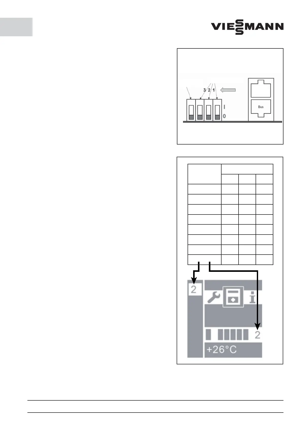
diagram). A bus address must also always be allocated to
each unit (binary code address on the controller board
via DIP switch, see circuit diagram). If the units should
be supplied with power via several electrical circuits,
external potential equalization is required (min. 6 mm²).
The potential di erence must not exceed 2 V. If this does
not occur, the data connection can be destroyed and the
cooling mode disrupted.
10.2 Bus operation modes
- Bus type: multi-cell
Up to eight coldrooms with di erent temperatures can
be managed on a display. To better allocate the units to
the rooms, the units can be given a name (see parameter
list).
- Bus type: redundant
The units run jointly in a coldroom with the same para-
meters. For FS and CS units, the model ‘wall-hanging unit’
must be selected (see parameter list). The model controls
the defrost function so that all units are simultaneously
defrosted. If the option ‘ceiling unit’ is selected, the units
defrost at di erent times. For wall-hanging units, this
would lead to ice formation.
10.3 Bus operation faults
In the event of outages within the network, the units
always continue running with the last parameters to be
transmitted from the display. When the connection is
restored, the system automatically adjusts.
10.4 Mains connection
The mains connection is located on the circuit board in
the housing. To connect the unit, the housing must be
opened and connected using a suitable data cable.
The control unit can be connected via a mains cable. The
connection occurs via a web browser and the appropriate
IP address. Access is gained by entering the username
‘admin’ plus the applicable authorisation number (1234
for users and 90210 for service personnel). Internet access
must be accordingly released. This occurs via the IT sup-
port team at the installation site.
Emergency
switchoff lower
"Off"
Switch for bus address
Display
and bus
Address
DIP switch
123
1
000
2
100
3
010
4
110
5
001
6
101
7
011
8
111
 Loading...