GB
General notice (liability): the details of this technical documents serve for description. Consents regarding the availability of certain features or
regarding a certain purpose always require a special written agreement.
Right reserved to make technical changes!Page 66 GB
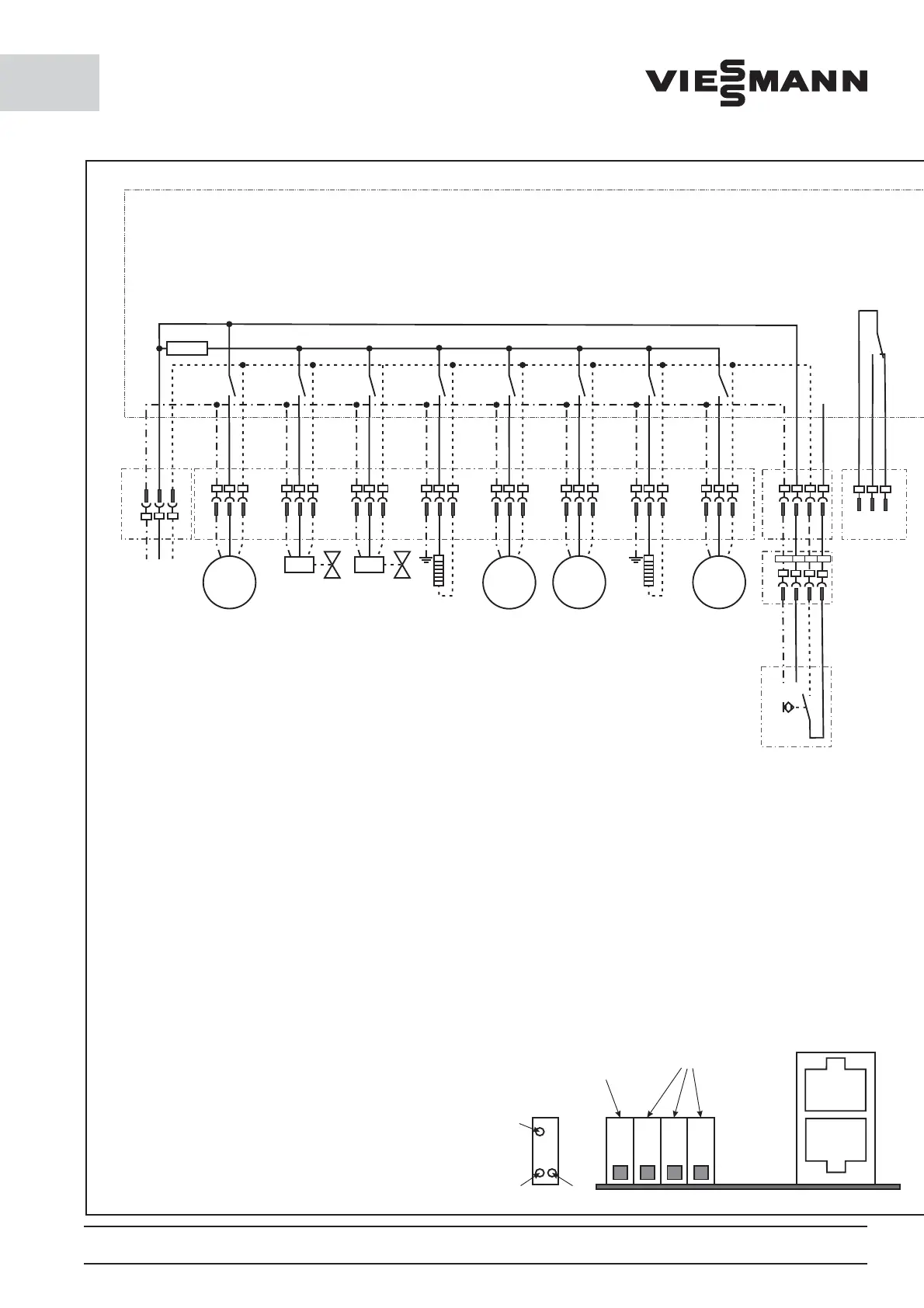
13. Electrical circuit diagram for 230V / 1~ / 50Hz
L
N
PE
F6,3Atr
Compressor
230V 1~
L
N
PE
Magnetic
valve
Hot gas
bypass
L
N
PE
Magnetic
valve
Fluid line
L
N
PE
L
N
PE
L
N
PE
Heating in
the defrost
water hose
(Heating in
the drip tray)
L
N
PE
L
N
PE
Evaporator fan
230V 1~
IN
NC
NO
X3D
X1
X3FX3E
X3H
X3G
X3CX3B
11
12
14
Alarm contact
potential free
Door element
(extract / optional)
X2
L
1
PE
N
PE L N
13
14
Door
contact
switch
Power board (Part number 00173920)
M
~
L
N
PE
M
~
M
~
M
~
X3A
Attention!
Before pulling a plug,
the equipment must be
brought to a zero potential status!
Contacts
JST plug
A1
A2
B1
Emergency
switchoff lower "Off"
Switch for bus address
Display
and bus
Bus
L
1
PE
N
GEYE
BU
BK
BN
4-pole
multi-contact
plug
1
2
3
0
I
Oil sump
heating
(optional)
X4
Electric supply
230 V AC 50 Hz
16 A K-characteristic
personal protection
measure FI
protection switch
Condenser
fan B
230V 1~
(optional)
Condenser
fan A
230V 1~
Attention! Please optional note on page 67
and 69 emergency operation.
 Loading...