General notice (liability): the details of this technical documents serve for description. Consents regarding the availability of certain features or regar-
ding a certain purpose always require a special written agreement.
GB
Right reserved to make technical changes!Page 67 GB
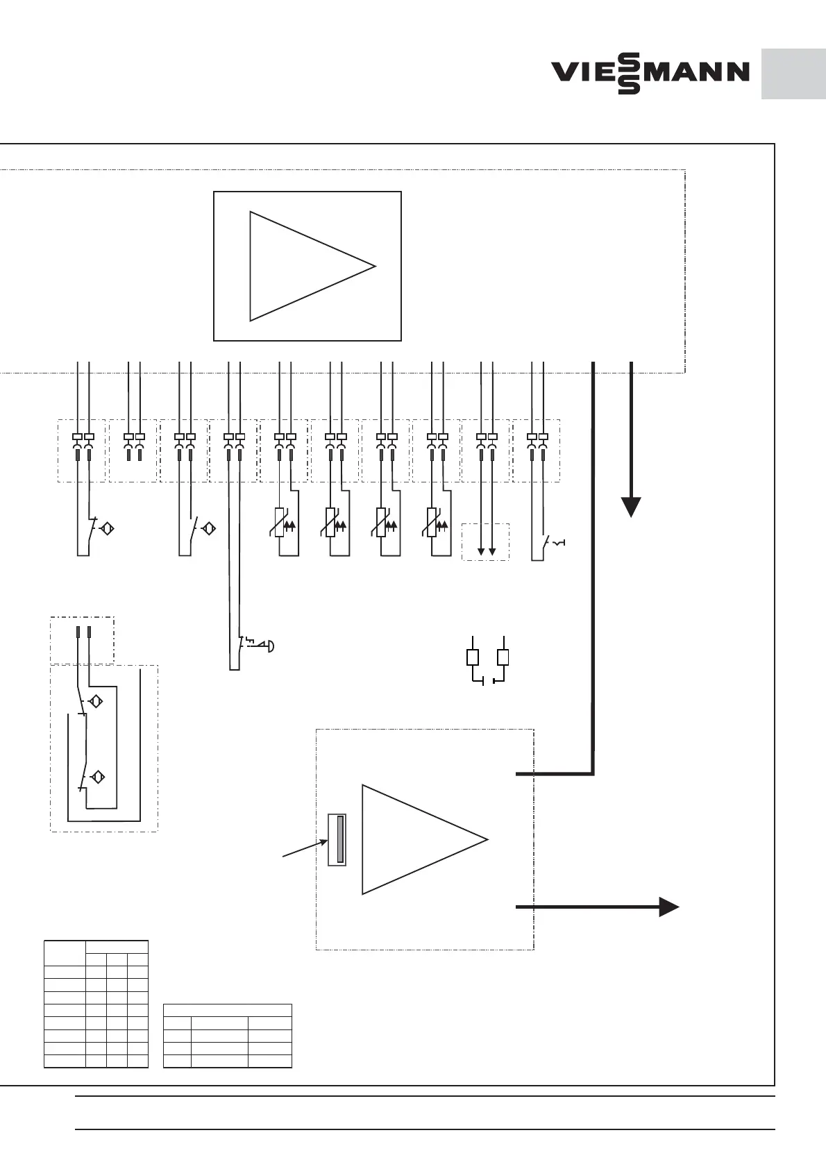
22
IN
12V+
Filter passage
switch liquefier
(optional)
11
IN
12V+
18
IN
12V+
17
IN
12V+
16
IN
12V+
15
IN
12V+
14
IN
12V+
13
IN
12V+
12
IN
12V+
21
IN
ND
HD
B
12
A
C
12
IN
X5 /12
Wiring in the case
of HD/ND switch
(optional)
Low
pressure
switch
12
11
12
13
High
pressure
switch
Evaporator
sensor
PT 1000
Condenser
sensor
PT 1000
Emergency
circuit
externally
(optional)
AOut+
GND
Data logger
detector
PT 1000
Room air
sensor
PT 1000
13
14
Fan speed
liquefier
A1
A2
A1
A2
A1
A2
A1
A2
A1
A2
A1
A2
A1
A2
A1
A2
A1
A2
A1
A2
Upper display and bus lower
bus (optional) RS 485 via
RJ 45 cable
Ethernet interface
RJ 45
USB port for
data exchange
Display (Part number 00173921)
+12V
X5 / 11
A1
IN
X5 /11
A2
123
1 000
2 100
3 010
4
110
5 001
6 101
7
011
8
111
DIP switch
Ad r e s s e
ϑ
ϑϑ
ϑ
GEYE green/yellow grün/gelb
BU blue blau
BN brown braun
BK black schwarz
conductor coloring
X5
Personal
protection
circuit
(optional)
Upper display and bus lower
bus (optional) RS 485 via
RJ 45 cable
Power lengths:
Power board / display max 8 m
Power board
/ Power board max. 15 m
Version 2012/11/30
00250227_0
1 Steuerung 1 phasig.cdr
Optional
for emergency
switch
21
9 Volt






 To Next Page