A
X5
X4
150
X1
E
X8
150
X2
D
150
X3
D
150
X7
D
654321654321
ON
ON
TR
TR
N
ON
ON
TR
TR
N
ON
ON
TR
TR
N
ON
ON
TR
TR
N
136
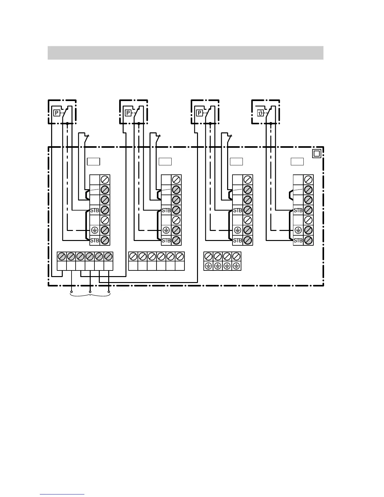
Components
Plug−in adaptor for external safety equipment (cont.)
Lower part of the plug−in adaptor
A Wiring chamber
B External safety equipment
X1 Additional high limit safety
cut−out, temperature limiter
or flue gas damper
X2 Minimum or maximum
pressure limiter
X3 Maximum pressure limiter
X7 Low water indicator
C External controlled shutdown
D Plug aBÖ
E Plug aBÖ of the control unit
F To the control panel or to the
reporting facility
G Connection for cable with
plug aBÖ to the control unit
H Remove the corresponding jumper
when connecting the external
safety equipment.
H When connecting a motorised flue
gas damper, plugaBÖ of the flue
gas damper is inserted into
socket"X1" of the plug−in adaptor.
Note
Every socket "X1", "X2", "X3" and
"X7" must contain a plug aBÖ.
5862730GB
 Loading...