159
Connection and wiring diagrams
Main PCB low voltage (cont.)
§ Boiler water temperature
sensor
% Cylinder temperature sensor
(accessories) / cylinder
temperature sensor 2 for a
cylinder storage system
aG Flue gas temperature sensor
(accessories)
aJA Temperature sensor of
Therm−Control
or
Temperature sensor T1
aJB Temperature sensor T2
or
Temperature sensor
cylinder storage system
aVD External hook−up
aVG KM BUS user (accessories)
aVH External hook−up
LON Interconnecting cable for data
exchange between control
units
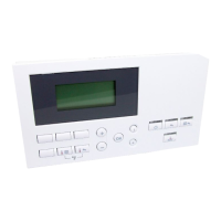
S3 Emissions test switch "S"
V1 Fault indicator (red)
V2 ON indicator (green)
5862730GB
 Loading...