12
Preparing for the control unit installation
Connections to the back of the control unit: See
boiler control unit installation instructions.
Note
■
Boiler water temperature sensor
§
is supplied in the
control unit pack.
■
Boiler coding card
A
is included in the product pack
(not used for thermostat control).
■
Insert the probe and the boiler water temperature
sensor as far as they will go into the sensor wells.
■
Power supply plug
fÖ
is supplied with the control
unit.
!
Please note
Damaged capillary tubes will result in faulty sen-
sor function.
Never kink the capillary tubes.
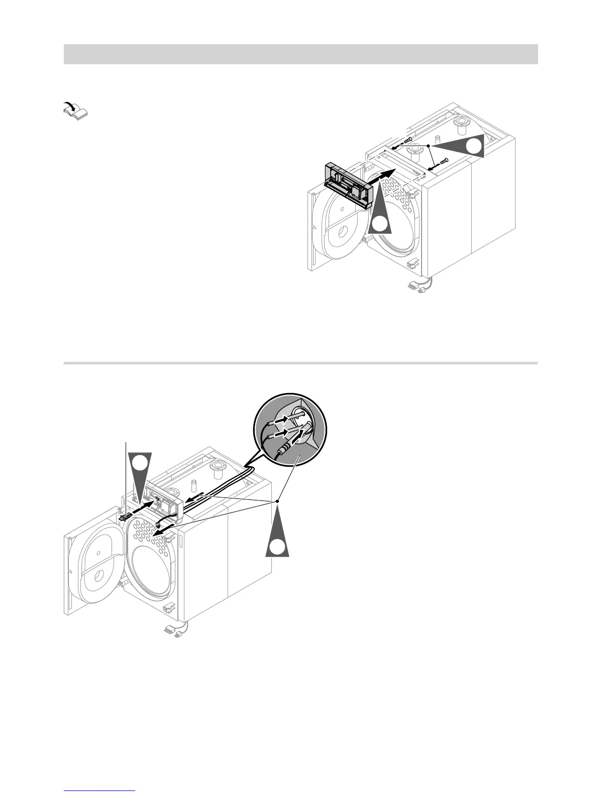
Fig. 12
Note
Screws (6 x 12) can be found with the control unit fas-
cia (packed separately with the thermal insulation).
Routing cables
Fig. 13
A
Boiler coding card
Note
Bundle and secure the LV cables.
Route 230 V cables and LV leads separately.
Fitting the thermal insulation (cont.)
5592 753 GB

 Loading...