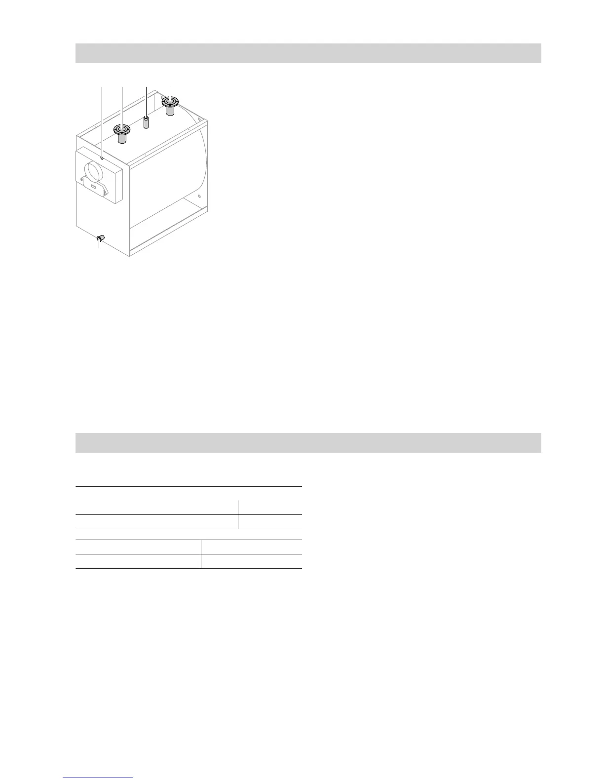
Fig. 5
A
Boiler return
for 150 to 310 kW: DN 65
for 400 to 620 kW: DN 100
B
Safety connection (safety valve), see page 7
C
Boiler flow
for 150 to 310 kW: DN 65
for 400 to 620 kW: DN 100
D
Female connection for boiler water temperature
sensor, high limit safety cut-out and temperature
controller
E
Drain, R 1¼
Making the safety connection and testing for tightness
Install the safety lines.
Safety connection
150 to 310 kW R 1¼
400 to 620 kW R 1½
Permiss. operating pressure 5 bar (0.5 MPa)
Test pressure 6.5 bar (0.65 MPa)
Low water indicator
According to EN 12828, a low water indicator can be
omitted for Vitoplex 100 boilers up to 300 kW (except
in attic heating centres), as the standard boiler control
unit prevents impermissible heating.
If required, install a low water indicator or a minimum
pressure limiter into the pipework.
Note
Equip the boilers with a safety valve that is type-tested
according to EN 4126. The valve must be marked in
accordance with the system version.
Install all pipe connections free of load and torque
stress.
!
Please note
Unsuitable water quality can damage the boiler
body.
Only fill the boiler with water that complies with
the "Water quality requirements" (see service
instructions).
Connections on the heating water side (cont.)
5592 753 GB

 Loading...