24
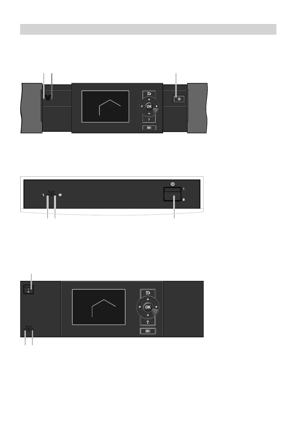
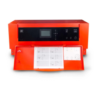
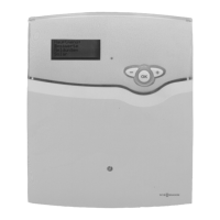
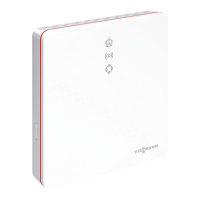
The heat pump control unit may look different depend-
ing on the type of heat pump.
Control unit at the front of the heat pump
Fig. 14
A
Fault indicator (red)
B
ON indicator (green)
C
ON/OFF switch
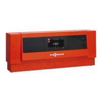
At the top of the heat pump
Fig. 15
A
Fault indicator (red)
B
ON indicator (green)
C
ON/OFF switch
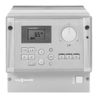
Control unit in a separate enclosure on the wall
Fig. 16
A
Fault indicator (red)
B
ON indicator (green)
C
ON/OFF switch
1. Switch ON the power supply, e.g. at a separate
MCB/fuse or a mains isolator.
Start-up/shutdown
Starting the heat pump
5790940








 To Next Page