35
ViewSonic Corporation Confidential - Do Not Copy PJ503D-1
4. Assembly LP Module
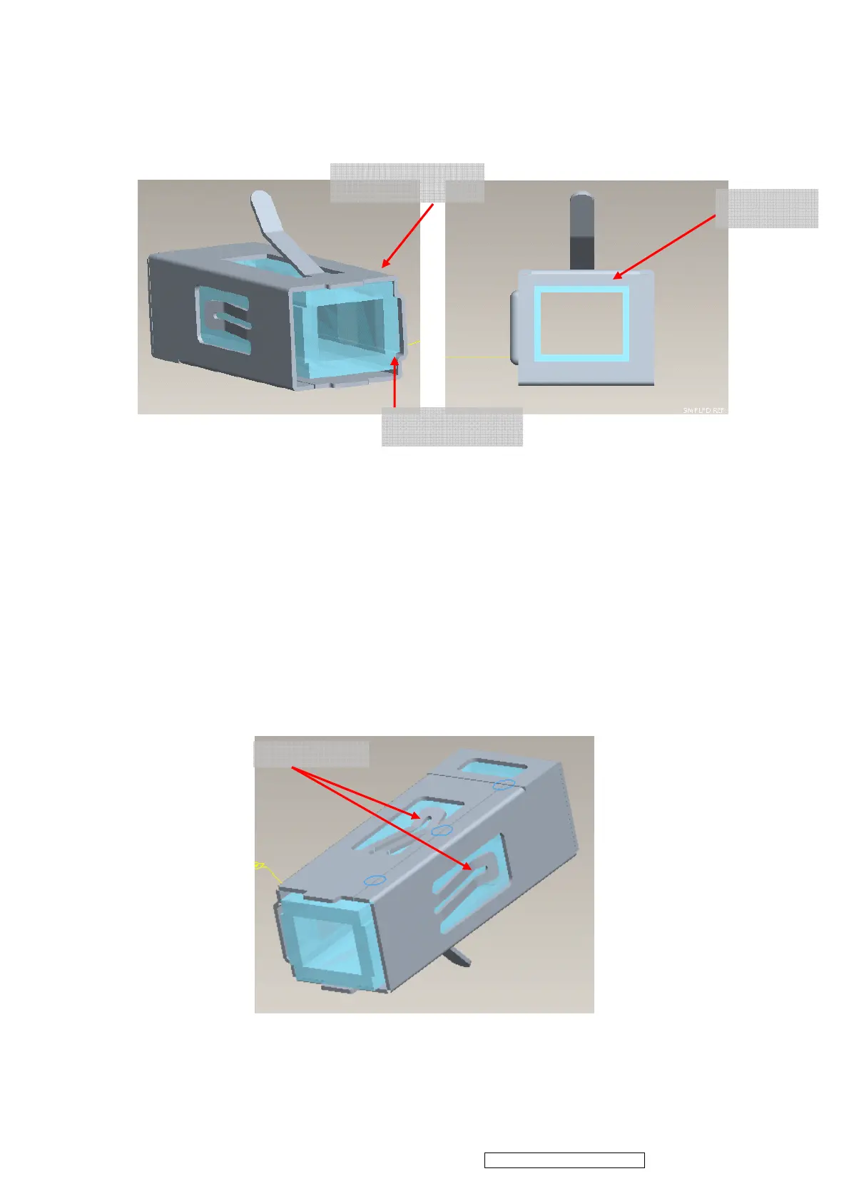
4.1 LP must datum well with “BKT_LP” show as Figure 4-1
4.2 Referring to Figure 4-2,there must be visible clearance between “BKT_LP” and ”LP
opening” after assembly。
Figure 4-1 Figure 4-2
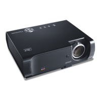
4.3 Glue “LP” and “BKT_LP” with “”UV5503 Glue” at two opening of “BKT_LP” show in Figure
4-3。
4.4 UV-5503 Glue curing process and concerns:
viii. The UV-glue must fill up the whole opening area (shown in Figure 4-3) to contact well
with LP surfaces and BKT_LP.
ix. Exposed to visible light at 350 ~ 420nm(at least 100mW/cm2) wavelength for 20
seconds.
x. After curing, the height of UV-glue should not exceed BKT_LP for more than 0.6mm
Figure 4-3
4.5 Assembly LP Module to HSG DMD
i. Assembly two Overfill adjustment screw (8F.1A752.8R0) to HSG DMD( Figure4-4)。
** Adjustment criteria refer to item 4.6.
Glue 5503
Clearance
TOP Datum
RIGHT Datum