36
ViewSonic Corporation Confidential - Do Not Copy PJ503D-1
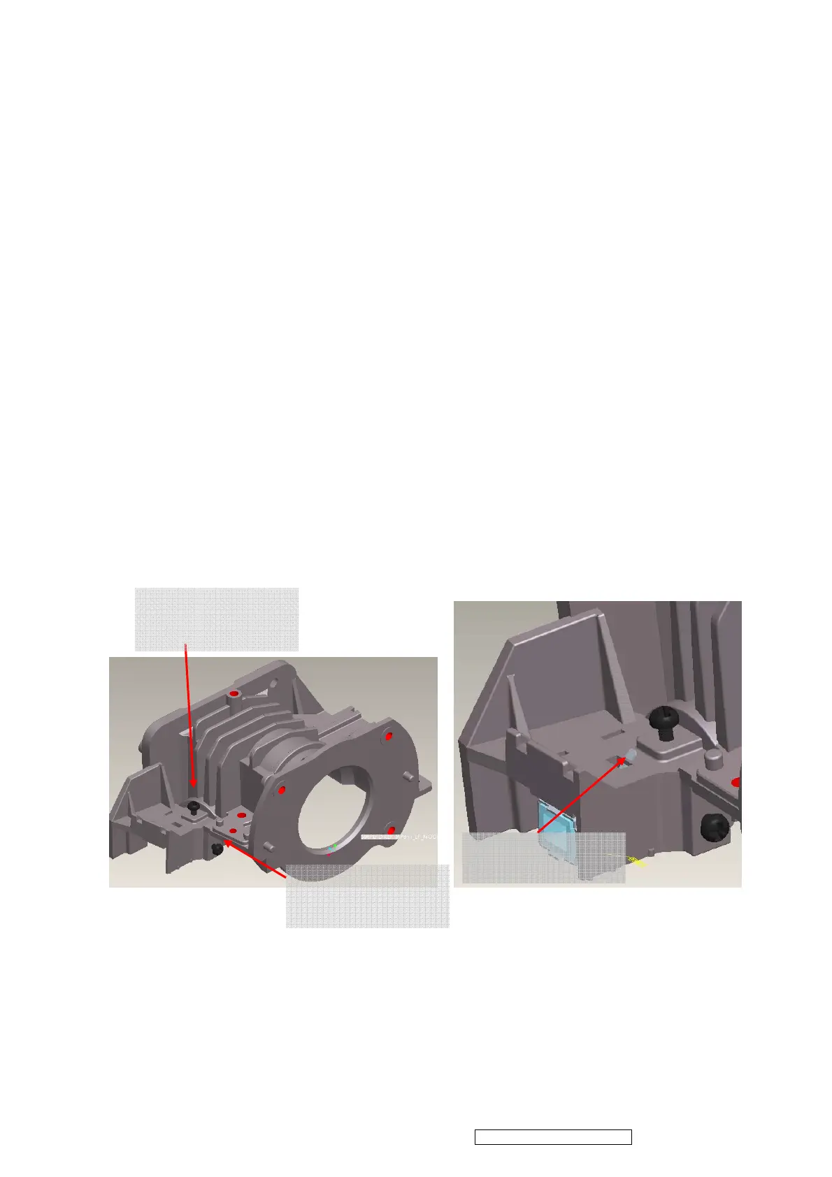
ii. Insert CLIP of BKT_LP into the hole
iii. Placed LP Module on LP datum and adjustment screw well, shown ( Figure 4-6)。
iv. Assembly “Baffle LP” first ( Figure 4-7)and make sure it hooks HSG DMD well
~ Assembly Criteria was shown in Figure 4-7-2.
v. Assembly “Clip_LP” second ( Figure 4-8)and make sure it hooks HSG DMD well。
( Figure 4-9)。
vi. Push two hook places to make sure that Baffle_LP touches “BKT_LP “well, don’t push
the middle place of “Baffle_LP”。
4.6 Overfill Adjustment @ LP Module
Overfill Adjustment Criteria:
i. Pre-assembly 2 adjusting screws. Criteria shown as Figure 4-10.
ii. Alignment Sequence:
a. To adjust “Horizontal Adjustment Screw” firstly, then “Vertical Adjustment
Screw”.
b. Refer to Figure 4-10.
For Overfill Re-adjustment:
1. Those 2 Adjustment Screws must be released closely to the “Pre-assembly”
positions first. (defined in 4.6-i )
2. Follow adjustment steps shown in Item 4.6-ii.
Figure 4-4 Figure 4-5
CLIP of BKT LP
(1) Overfill Horizontal
Adjustment Screw
(1) Overfill Vertical
Adjustment Screw