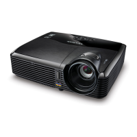
Optical Engine Assembly and Alignment Concerns
1. Light Pipe Module assembly and overfill alignment
1.1 Assembly LP Module to HSG DMD
i. Assembly two Overfill adjustment screws to HSG DMD (Fig. 1-1).
** Adjustment criteria refer to below item 1.5 & Fig. 1-2.
ii. Assembly “Clip LP” and lock with screw well (Fig. 1-3).
iii. Press CLIP of RE_BKT_LP first, and then push it into the hole (Fig. 1-4).
iv. Placed LP Module on LP datum of “DMD HSG” and adjustment screw well, shown
(Fig. 1-5).
v. Assembly “Baffle LP” first (Fig. 1-6) & push “Baffle LP” to hook DMD HSG(Fig. 1-7),
vi. When Lock the screw of Baffle LP ,the hand must push the left corner of Baffle LP
before (Fig. 1-8),.
vii. Lock the screw of Baffle LP well then release the hand (Fig. 1-9),
1.2 Overfill Adjustment @ LP Module
Overfill Adjustment Criteria:
i. Pre-assembly 2 adjusting screws. Criteria shown as Fig.1-2
ii. Alignment Sequence:
a. To adjust “Horizontal Adjustment Screw” firstly, and then “Vertical
Adjustment Screw”.
b. Refer to Fig. 1-2
1.3 For Overfill Re-adjustment:
a. Those 2 Adjustment Screws must be released closely to the “Pre-assembly”
positions first (Fig. 1-2).
b. Follow adjustment steps shown in Item 1.5-ii..
Fig. 1-1
Overfill Vertical
Adjustment Screw
Overfill Horizontal
Adjustment Screw
Confidential - Do Not Copy
PJD5122
ViewSonic Corporation

 Loading...
