®
© 2009 Viking Preferred Service
19
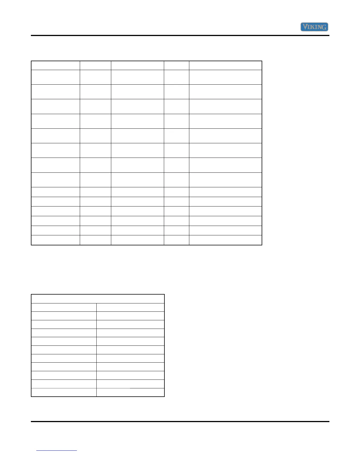
Component Testing
Component Volts Ohms Amps Test Location
Thermostat Timer 120 0 N/A AT1 (BK) to AT2 (WH) @
thermostat timer
RTD 5 VDC 1100 Ω @ 75˚ N/A AT5 to AT6 @ thermostat
timer
Selector Switch 120 Infinite N/A BA to 2 @ selector switch
with bake not selected
Selector Switch 0 0 N/A BA to 2 @ selector switch
with bake selected
Selector Switch 120 Infinite N/A BR to 1 @ selector switch
with broil not selected
Selector Switch 0 0 N/A BR to 1 @ selector switch
with broil selected
Selector Switch 120 Infinite N/A CV to 3 @ selector switch
with convection not selected
Selector Switch 0 0 N/A CV to 3 @ selector switch
with convection selected
Bake Igniter – RH 120 135 N/A Bake igniter RH
Bake Igniter – LH 120 91 N/A Bake igniter LH
Broil Igniter 120 106 N/A Broil igniter
Dual Bake Valve 3.2 – 3.6 1.2 3.2 Bake valve
Broil Valve 3.2 – 3.6 1.2 3.2 Bake valve
Convection Motor 120 29.8 N/A Convection motor
The chart shown here is a Temp-to-Resistance Chart for RTD.
The oven sensor is also know as a P.T.C. (Positive Temperature Control) device which means that as the
temperature rises, the resistance increases.
RTD (Resistive Thermal Service)
Temperature (˚F) Resistance (approximate)
50 1038
75 1090
100 1143
200 1350
300 1553
350 1654
400 1754
450 1852
500 1950
550 2047
Service Diagnostics and Procedures