®
© 2009 Viking Preferred Service
22
Convection Fan Motor Testing
The oven utilizes a 120VAC convection fan motor to
move air through the cavity. When the convection
fan motor is required, power is supplied from the
thermostat through selector switch.
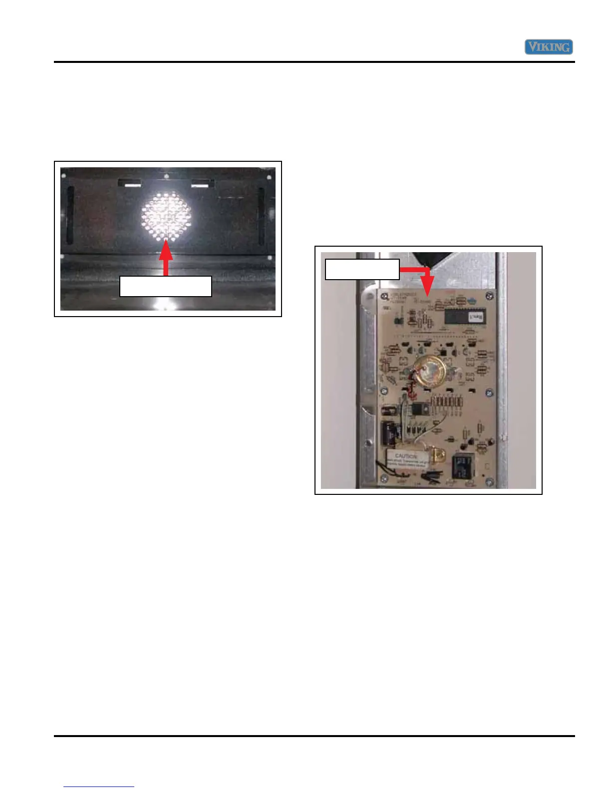
To access the convection fan assembly, remove the
oven door, oven racks, and convection fan cover.
The assembly is now accessible and can be removed
from inside the oven cavity.
Line power comes from terminal AT3 of the
thermostat timer, to terminal CV of the selector
switch, through closed contact CV to 3 to the
convection fan motor. Neutral is supplied via the
power cord. With Volt-Ohm meter set to voltage
and selector switch set to convection, measure the
voltage at the convection fan motor (RD – WH).
If 120 VAC is present and the fan is not turning,
replace the convection fan motor. If no voltage is
present, verify contact CV-3 is closed at the selector
switch. If the contact is closed, verify 120 VAC
to ground from thermostat timer terminal AT3.
If voltage is present,
check wiring and repair or
replace as necessary. If no voltage is present, verify
120 VAC between thermostat timer AT1 and AT2. If
voltage is present, replace the thermostat timer.
Thermostat Timer Testing
The operation of the oven is achieved by input
from the thermostat timer to the selector switch.
The thermostat timer receives power directly from
the line cord at positions AT1 (L1) and AT2 (N).
Power is transferred from the thermostat timer
to the selector switch. Line power comes from
the thermostat timer (AT4) to the selector switch
terminal BA (bake) and BR (broil) via a black wire.
Line power comes from the thermostat timer (AT3)
to the selector switch terminal CV (convection) via a
black wire.
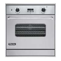
To access the thermostat timer, open oven door
and remove screws securing control panel. Slide
unit out 6 – 8” and remove screw from right side
trim securing control panel. Remove nut securing
oven light switch, selector switch knob, and timer
buttons. Remove control cover and disconnect
wiring. Separate the control cover by removing
securing screws. The thermostat timer is now
accessible.
The thermostat timer receives line power via
terminal AT1 (double black wire) directly from the
line cord. Neutral is supplied by the line cord at
terminal AT2 (double white wire). The thermostat
timer receives input from the sensor at terminals
Convection Fan
Thermostat
Service Diagnostics and Procedures