7
c
a
d
b
c
f
c
a
b
7511020
FIG.8
FIG.6
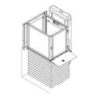
Control panels - Fig. 6
The control panel on the side guard carries the fol-
lowing:
- Emergency Button (Fig. 6/a)
- Key (Fig. 6/b)
- Up and down control buttons (Fig. 6/d)
- Alarm button (Fig. 6/c)
The rail opposite guard can carry the wireless control
panel (Fig. 7) equipped with up/down buttons (Fig. 7/a)
and key (Fig. 7/b).
3.2) Main mechanical safety features
- Gates can be opened from the outside with a special
key.
- Movement cuts out in the event of obstacles under-
neath the platform.
- Over-run device.
- Safety gear/bush.
- Photocell barriers (option)
3.3) Main electrical safety features
- STOP button on board the lift.
- Safety microswitch with over-run.
- Dual system to ensure gate closure with lock and
tamperproof microswitch.
- Movement cuts out in the event of nut screw failure.
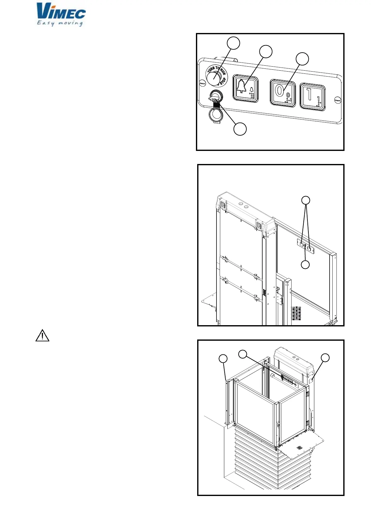
3.4) Warning signs
The lift is tted with various warning signs:
- Nameplate stating rated payload (Fig. 8/f).
- Nameplate stating payload and those permitted to
use the lift (Fig. 8/c).
The lift system must be installed by skilled
staff authorised by VIMEC.
3.5) Reference Directives
The lift complies with the following directives:
- 2004/108/EEC “Electromagnetic Compatibility”
Directive
- 2006/95/EEC “Low Voltage” Directive
- 2006/42/EEC “Machinery Directive”
FIG.7
7512020
 Loading...