7602040
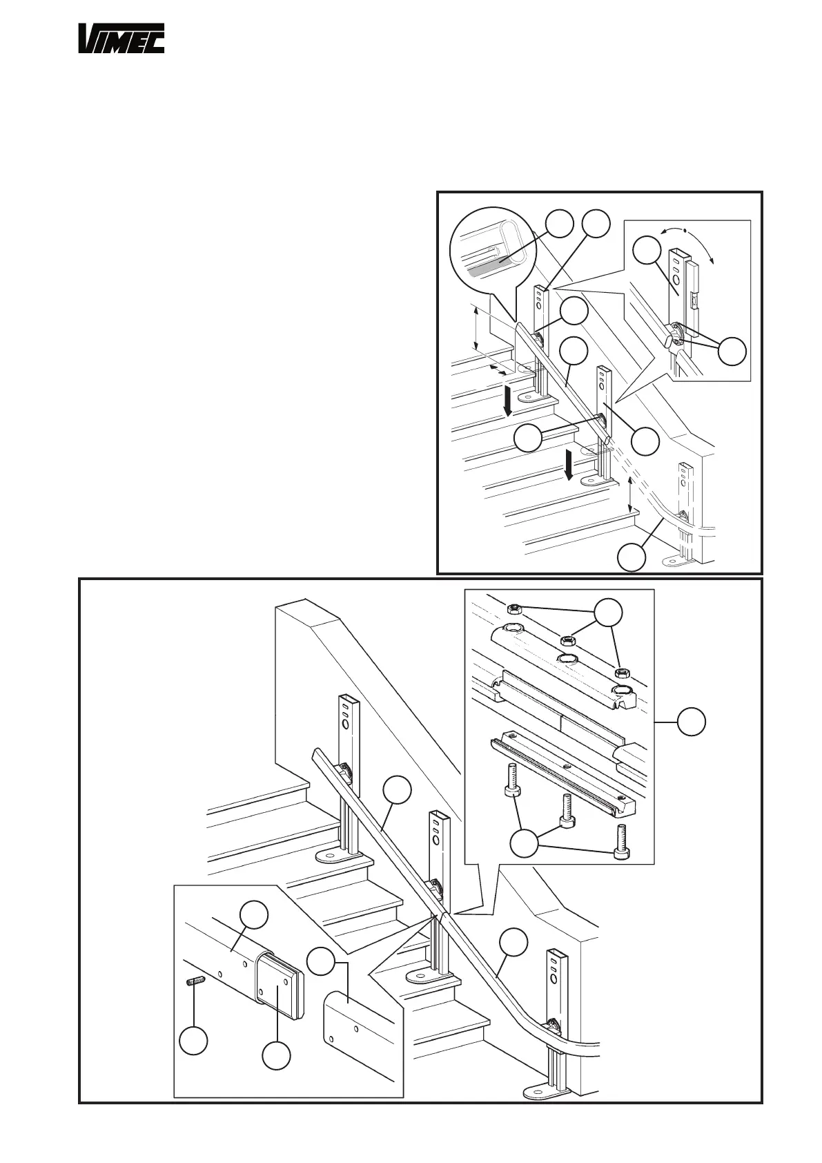
- Set the bend connection fixtures perfectly vertical
(Fig. 7) and tighten both the fixing screws once adjust-
ment is complete (Fig. 7/a).
N.B.: Check that the part of the lower rail (Fig. 8/g)
on which the brushes operate is clean, and remove
any dirt if necessary.
WARNING: The rail fixing screws (Fig. 7/a) must be
tightened to a torque of 9-10 daNm.
- Use the assembly markings (Fig. 3/b) to identify the
section of rail with feet (Fig. 8/a) to be placed just
above the bend just installed (Fig. 8/b).
- Position the rail correctly for installation (Fig. 8/a),
referring to the dimensions shown in the installation
drawing (example Fig. 5), extract the feet and lightly
tighten just one bolt (Fig. 8/c) for each connection
fixture (Fig. 8/d).
- Fit the joint plates (Fig. 9/e) into the tubular rail
(Fig. 9/ a) and lightly tighten the first 2 stud bolts
(Fig. 9/f).
- Place the next section of rail working downwards
(Fig. 9/b) in position, fit the other stud bolts and tighten
to a torque of 4-5 daNm after checking that the tubular
rails are correctly aligned and there is no gap between
the rail sections. Fit the busbar connection joint as
shown (Fig. 9/d) after checking that the components
are clean.
- Following the procedure already used for the bend,
set the connection fixtures (Fig. 8/e) perfectly vertical
and tighten both the fixing screws once adjustment is
complete (Fig. 8/f).
- Install all the sections of rail except the last one as
just described, down to the bottom of the staircase.
FIG.8
FIG.9
± 1°
max
19
C
D
A
e
f
d
a
b
c
d
c
g
h
g
d
c
c
e
b
f
a
± 1°
max
 Loading...


