7602040
6) CONNECTING THE POWER SUPPLY UNIT
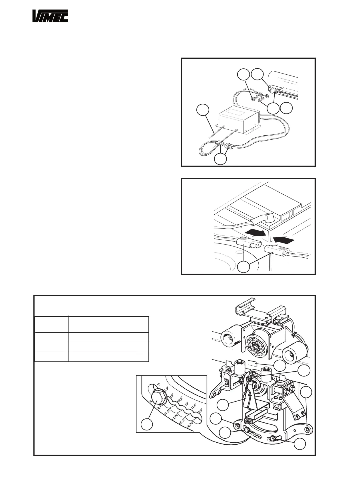
- Connect the wires (positive and negative) to the
busbar terminal provided, fixed to the rail (Fig. 27/a-
Fig. 27/b).
- Connect the 230 V 50 Hz power supply to the power
socket (Fig. 27/c).
- After installation, power up the system by connecting
the plug (Fig. 27/d).
- Connect the battery connector on the lift (Fig. 28)
and turn the on-off key on the casing to ON (Fig. 33/a
in use and maintenance manual). Once the lift has
been switched on, remove the key and keep it with
the documentation, the manual operation handwheel
and the arm release Allen key.
7) CONNECTING THE INSTALLATION ENGINEER’S
CONTROL PANEL
- Place the installation card (Fig. 29/b) in the slot
(Fig. 29/c) and connect the control panel (Fig. 29/a)
to the connector provided.
- Access the “Position” subroutine.
- Press “Enter”.
- Type the “Password”.
- From the “Control from console” menu.
- Press “Enter”.
- “UP” to ascend, “DOWN” to descend.
- Temporarily fit the magnet to the rail (Fig.26/a) in line
with the home floor recognition sensor (Fig.26/b). Then
press the UP button once to acquire the home floor
position and allow the lift to move.
FIG.27
FIG.28
FIG.26
DRIVING TORQUE
(daN x m)
POS.
25
a
a
-
b
-
c
d
2
1
2
3
3
3
a
b
1
2
3
2,5
6,0
4,5
 Loading...


