7602040
FIG.29
FIG.30
FIG.31
N.B.
:
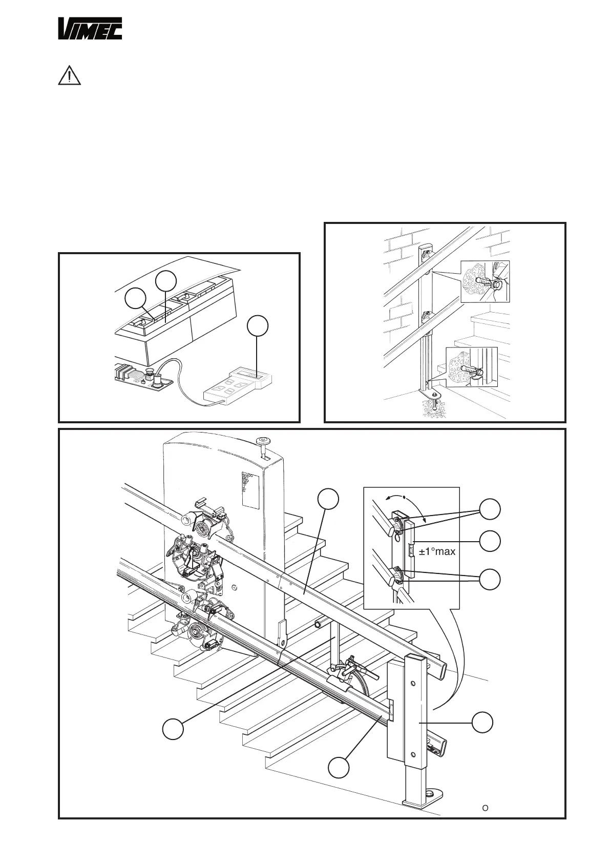
Move the lift up to the 1st rigid connection and if it
is not horizontal, screw down the M10x30 screw (Fig.
15/a) with washer (Fig. 15/b) onto the clutch assembly
to release the upper carriage from the clutch assembly.
The gap is correct when the clutch assembly cam is
about 2 mm from the carriage (Fig. 15/c).
- Move the lift up a short way to allow it to settle back
into position.
- Undo the screw (Fig. 15/a) and its washer (Fig. 15/b)
to re-engage the clutch plate assembly with the car-
riage.
WARNING: all safety devices are deac-
tivated (the operator is responsible for ensuring
safety).
-
Use the UP and DOWN controls on the control panel
(Fig. 29/a) to bring the structure, complete with car-
riage, to the chosen floor, in order to continue as-
sembly operations in complete safety.
- Fit the spacer (Fig. 30/g) between the rails and install
the connection/foot (Fig. 30/a).
- After setting the rail at the correct distance (Fig. 30/b
– Fig. 30/c) using the spacer (Fig. 30/g), and after
checking that the components are vertical (Fig. 30/a)
tighten the screws firmly (Fig. 30/e and Fig. 30/f).
26
c
b
a
c
f
d
e
g
b
a
 Loading...


