7602040
FIG.54
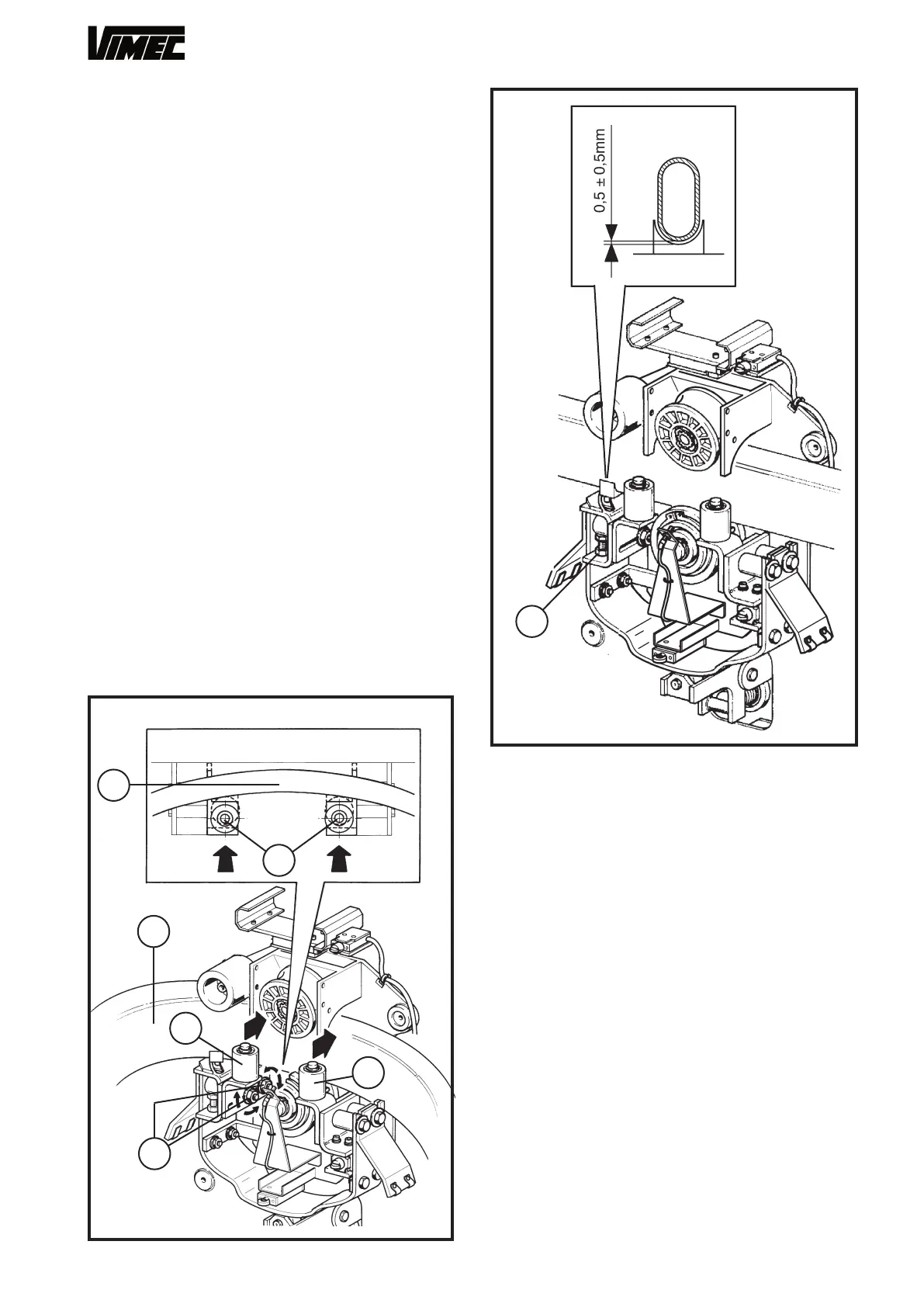
FIG.55
15) ADJUSTING THE BEND ROLLERS
Working on the bend with the lowest gradient (Fig. 54/
a), set the bend rollers in contact with the rail (Fig.
54/b). After adjustment, tighten the roller fixing screws
(Fig. 54/c) to a torque of 2 daNm.
This adjustment will be maintained for the other
bends
Check that the lift travels smoothly, with no bumps or
vibrations on the bends.
16) ADJUSTING THE GUIDE SHOE SUPPORTS
Use the screw (Fig. 55/a) to adjust the guide shoe
supports to obtain a gap of 0.5 ± 0.5 mm between the
guide shoe and rail (see Fig. 55).
35
a
b
a
b
c
b
a
 Loading...


