7602040
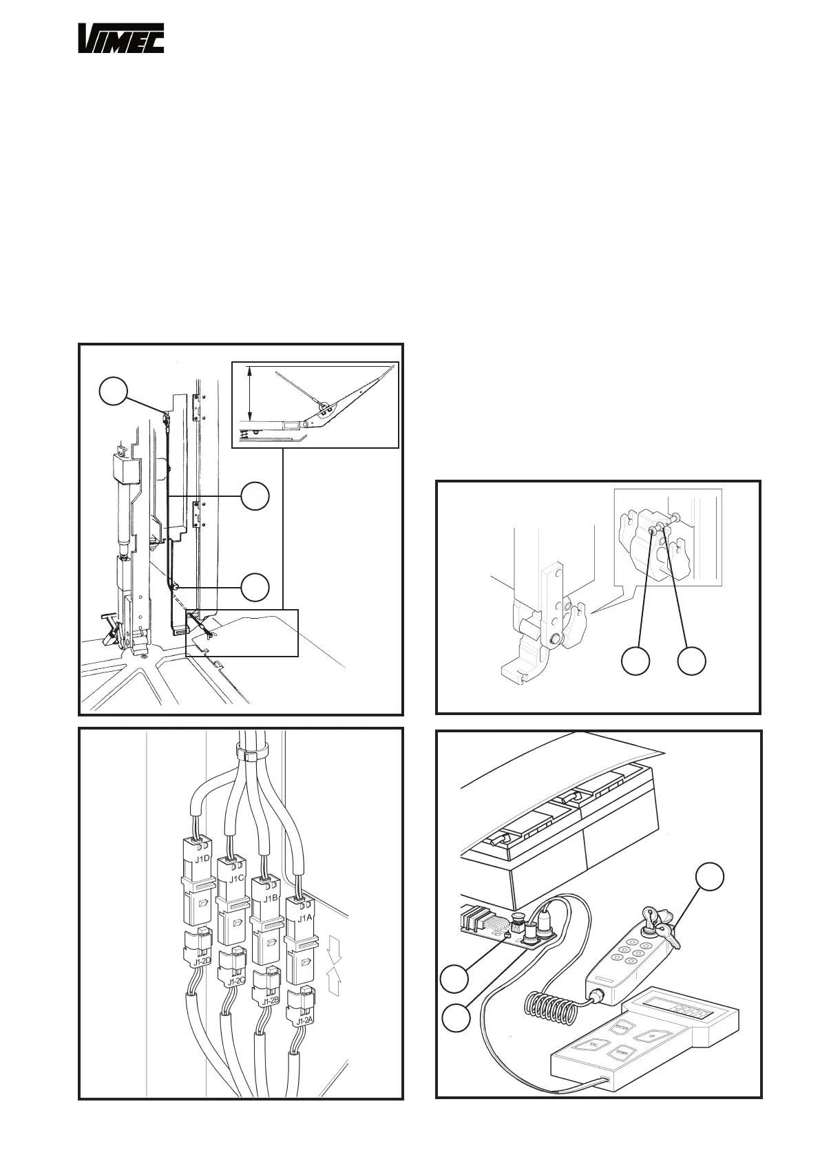
f) Connect the wires (Fig. 49/c) to the side flaps, pass-
ing them around the pin (Fig. 49/a).
If the flaps do not open or close correctly, adjust to the
correct position using the adjuster fork (Fig. 49/b).
g) Close the platform by replacing the cover plate and
the fixing screws.
h) Remove the wedge and plastic band (Fig. 46/c,d)
used to hold the platform horizontal during adjustment
from the platform supports.
i) Tighten the nut and locknut to a torque of 4 daN ± 0.1
(Fig. 51/a,b).
I) Connect the connectors J1A, J1B, J1C and J1D
(Fig. 50).
12) PREPARING THE LIFT FOR SETUP
When installation of the lift’s mechanical parts is com-
plete, the on-board control panel (Fig. 52/b) must be
added to the installer card (Fig. 52/a).
Reset the lift using the switch provided (fig.52/c), re
-
move the magnet from where it was placed temporarily,
then press the down button on the on-board control
panel; the lift will now descend at low speed, looking for
the magnet, which must be placed on the rail in such a
position that the home floor sensor detects it in line with
the exact access position (all subsequent operations will
take the position of this magnet as reference).
Glue the magnet (Fig. 53/a) supplied to the bottom end
of the top rail as shown in Fig. 53.
FIG.51
FIG.52
FIG.50
FIG.49
33
a
b
125
c
b
a
c
ab
 Loading...


