2
苏州万佳电器有限公司
Suzhou wanjia Electric Co.,Ltd.
The push-assist control and indication
Error code indication
Various Parameters Setting/Info (e.g. wheel size info, speed limit info, etc.)
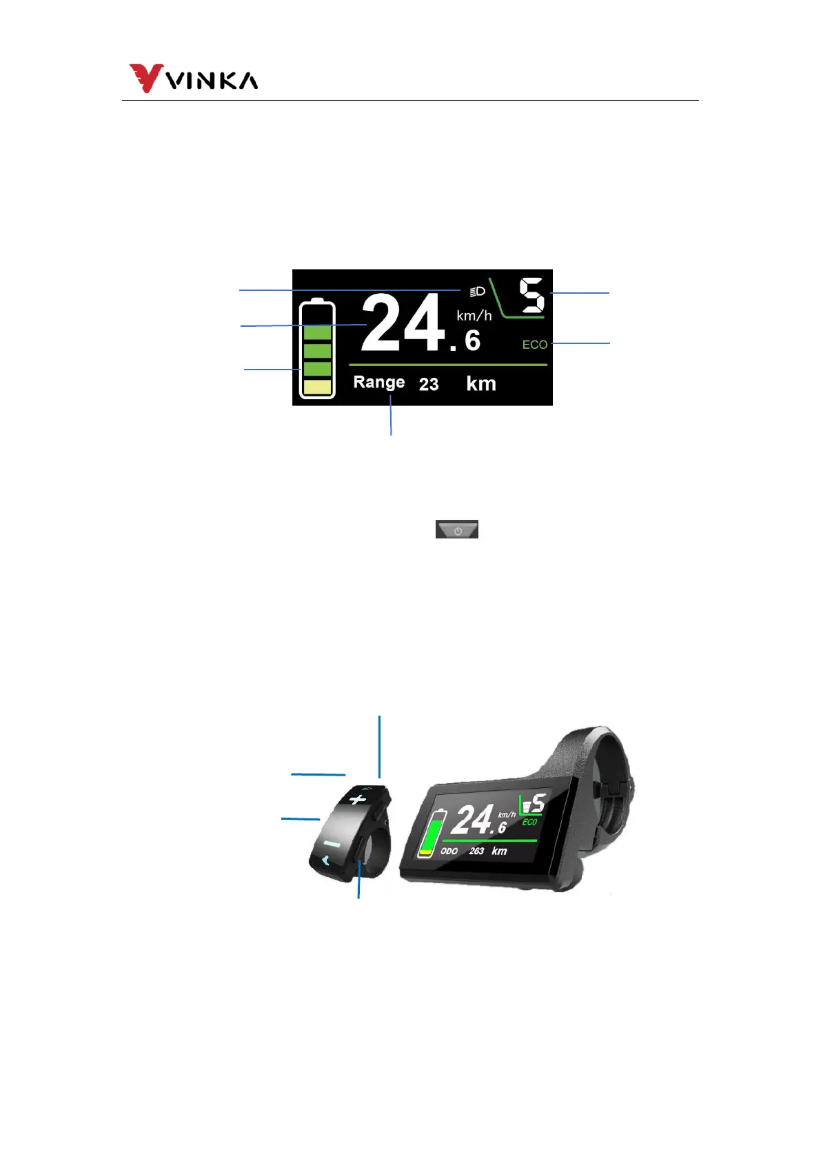
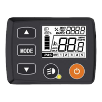
5. Function Area Distribution
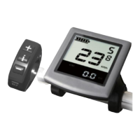
6. Button definition
DC31 has four buttons. Power button is on the top of the right button.
MODE button “i” is on the lower of the right button. Light/plus button “+”, , and minus
button “-” are on the independent left button. In this manual we use words “ON/OFF”,
“UP”, “MODE” and “DOWN” to represent these 4 buttons.
7. Installation
DC31 can be mounted on the middle of the two handlebars. Adjust the angle for
a good screen view. Cut off the power before connecting the corresponding
connectors between the display and controller.
Cadence/total mileage/Maximum speed
/average speed/ Riding time/Trip indication
Assist-level/Push-assistance
indication