User’s Manual
3. Connectors and Switches
The following describes the connectors and pins of the ESERV-10.
Serial Port (RS-232, RS-422/485 -connector)
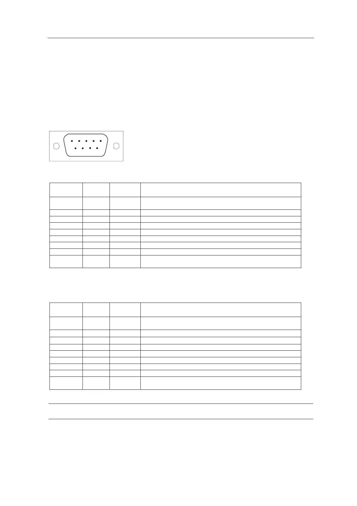
Serial connector is a 9-pin male connector (DB9). A null modem cable can be used to connect the
ESERV-10 to a device or a PC. The ESERV-10 supports CTS/RTS flow control. The figure of
ESERV-10’s DB9 (DTE) Male connector is shown below:
1
5
6
9
The pin description in case of RS-232 -connector is following:
Pin
Number
Name Direction Explanation
1 NC/PSU (IN/OUT) Pin can be used as an optional power supply (+) for ESERV-10
or the target device.
2 RXD IN Receive data
3 TXD OUT Transmit data
4 NC Not connected
5 GND - Signal ground
6 NC Not connected
7 RTS OUT Ready To Send. Handshake output
8 CTS IN Clear To Send. Handshake input
9 NC/PSU (IN/OUT) Pin can be used as an optional power supply (-) for ESERV-10 or
the target device.
In case of RS-422/485 the pin description is as follows
Pin
Number
RS-422
RS-485
Direction Explanation
1 NC/PSU (IN/OUT) Pin can be used as an optional power supply (+) for ESERV-10
or the target device.
2
RXD
+
IN Non-inverted data input
3
TXD
–
OUT Inverted data output
4 NC NC Not connected
5 NC NC Not connected
6 NC NC Not connected
7 TXD+ OUT Non-inverted data output
8 RXD- IN Inverted data input
9 NC/PSU (IN/OUT) Pin can be used as an optional power supply (-) for ESERV-10 or
the target device.
Note: Make sure that you do not connect RS-422 or RS-485 devices to port that is configured as
RS-232.
ESERV-10 11 Viola Systems Ltd.