User’s Manual
Ethernet Connector
The ESERV-10 contains an RJ45 connector for 10 Mbps Ethernet connection. ESERV-10 can be
connected with a direct Ethernet cable to a local network’s hub or switch. Maximum distance
between the board and the hub/switch is 100m. ESERV-10 can be connected directly to a PC
network interface card with a cross-connected Ethernet cable for testing.
Note: The cross-connected cable is only for connecting the ESERV-10 to the PC’s network
interface card. When connecting to a local network a direct Ethernet cable must be used.
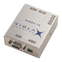
The figure and pin description of ESERV-10’s RJ45 Ethernet connector is following
18
Pin
Number
Name Direction Explanation
1 Rx+ IN Receive data
2 Rx– IN Receive data
3 Tx+ OUT Transmit data
4 NC
5 NC
6 Tx– OUT Transmit data
7 NC
8 NC
DIP Switches
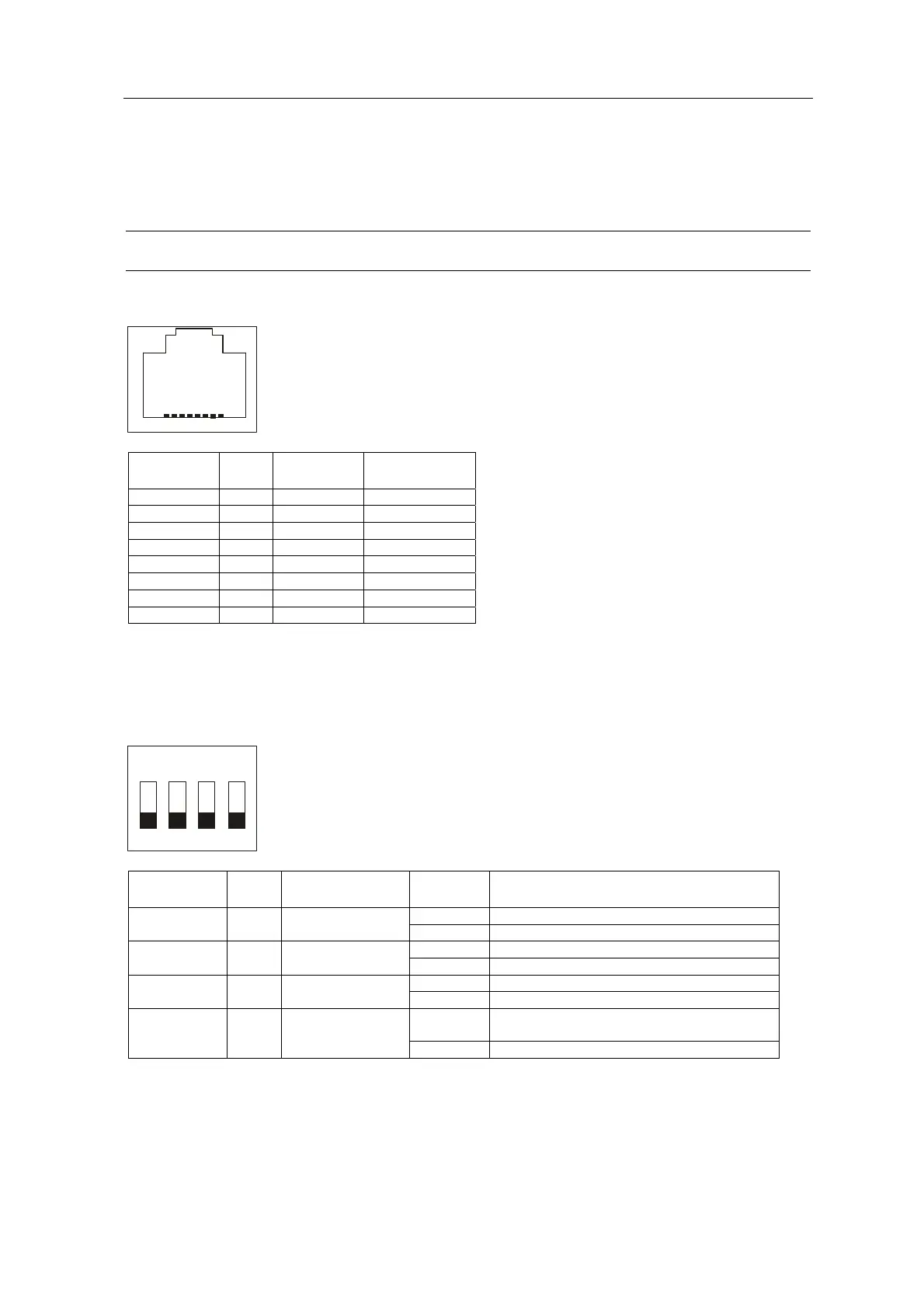
The ESERV-10 contains DIP switches for initialization and mode selection. The description of the
switch functions is as follows:
12
3
4
ON
Switch
Number
Name Function Position Description
ON Processor reset* 1 RST Processor reset
OFF Normal position
ON RS-485/422 mode 2 Mode RS mode selection
OFF RS-232 mode
ON Programming state** 3 Prog Programming
mode
OFF Normal position
ON Initializes programmable parameters and
clears IP address
4 Init Initialization
OFF Normal position
*NOTE: When resetting the processor switch momentarily ON and back OFF.
**NOTE: To enter programming mode set Switch 3 to ON position and reset the processor. This
forces the serial mode to RS-232.
ESERV-10 12 Viola Systems Ltd.