- 13 -
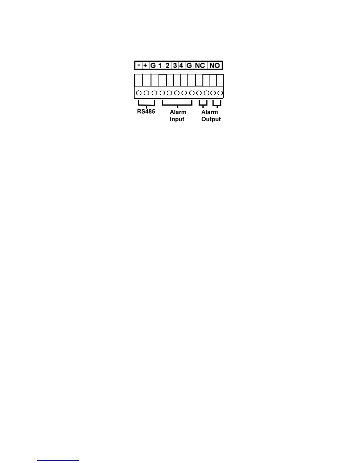
8. Alarm Input Connectors (ALARM IN 1-4)
Connect these connectors to external devices such as sensors or door
switches.
9. Alarm Output Connectors (ALARM OUT NC(1)/NO(2))
Connect NC connectors (left) to Normally Closed (NC) alarm output, or
NO connectors (right) to Normally Open (NO) alarm output. Please note
that only one of the NC or NO connectors can be connected only.
10. I/R Extension Connector (I/R, optional)
Optional I/R extension connector to receive signal from I/R remote
controller.
11. Power Switch (POWER)
Turn the power of this unit on/off.
12. Power Cord Inlet (DC 12V)
Connect to DC +12V power source.