Manual VIPA CPU 21x Chapter 5 Deployment CPU 21x-2BT02 with H1 / TCP/IP
HB103E - Rev. 05/45 5-39
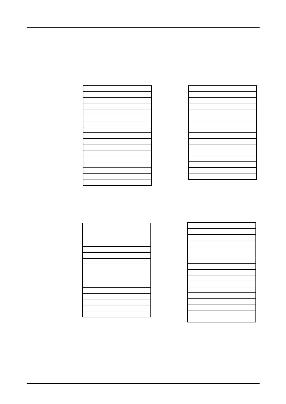
For every READ and WRITE the CP generates PLC headers for request
messages and for acknowledgment messages. Normally the length of
these headers is 16Byte and they have the following structure:
Structure of PLC
header
for WRITE
Acknowledgment message
System identifier ="S"
="5"
Header length =16d
Ident.OP code =01
OP Code length =03
OP Code =04
Ack. Block =0Fh
Ack. Block length =03
Error No. =No.
Dummy block =FFh
Dummy block length =07
not used
Request message
System identifier ="S"
="5"
Header length =16d
Ident.OP code =01
OP code length =03
OP Code =03
ORG block =03
ORG block length =08
ORG identifier
ERW identifier
Start address H
L
Length H
L
Dummy block =FFh
Dummy block length =02
64K data only if error no.=0
Acknowledgment message
System identifier ="S"
="5"
Header length =16d
Ident.OP code =01
OP Code length =03
OP Code =06
Ack. block =0Fh
Ack. Block length =03
Error No. =No.
Dummy block =FFh
Dummy block length =07
not used
64K data only if error no.=0
for READ
Request message
System identifier ="S"
="5"
Header length =16d
Ident.OP code =01
OP Code length =03
OP Code =05
ORG block =03
ORG block length =08
ORG identifier
ERW identifier
Start address H
L
Length H
L
Dummy block =FFh
Dummy block length =02