Manual VIPA CPU 21x Chapter 2 Hardware description
HB103E - Rev. 05/45 2-21
In addition to the components described in the section on the CPU 21x the
CPU 21xSER-2 module is provided with more LEDs and two serial RS232C
interfaces.
The LEDs are located in the left half of the front panel and they are used
for diagnostic purposes. The following table shows the color and the
significance of these LEDs.
Name Color Description
RN green Communication processor runs
ER1 red Error Interface 1
Rx1 green Interface 1 receive data
Tx1 green Interface 1 transmit data
ER2 red Error Interface 2
Rx2 green Interface 2 receive data
Tx2 green Interface 2 transmit data
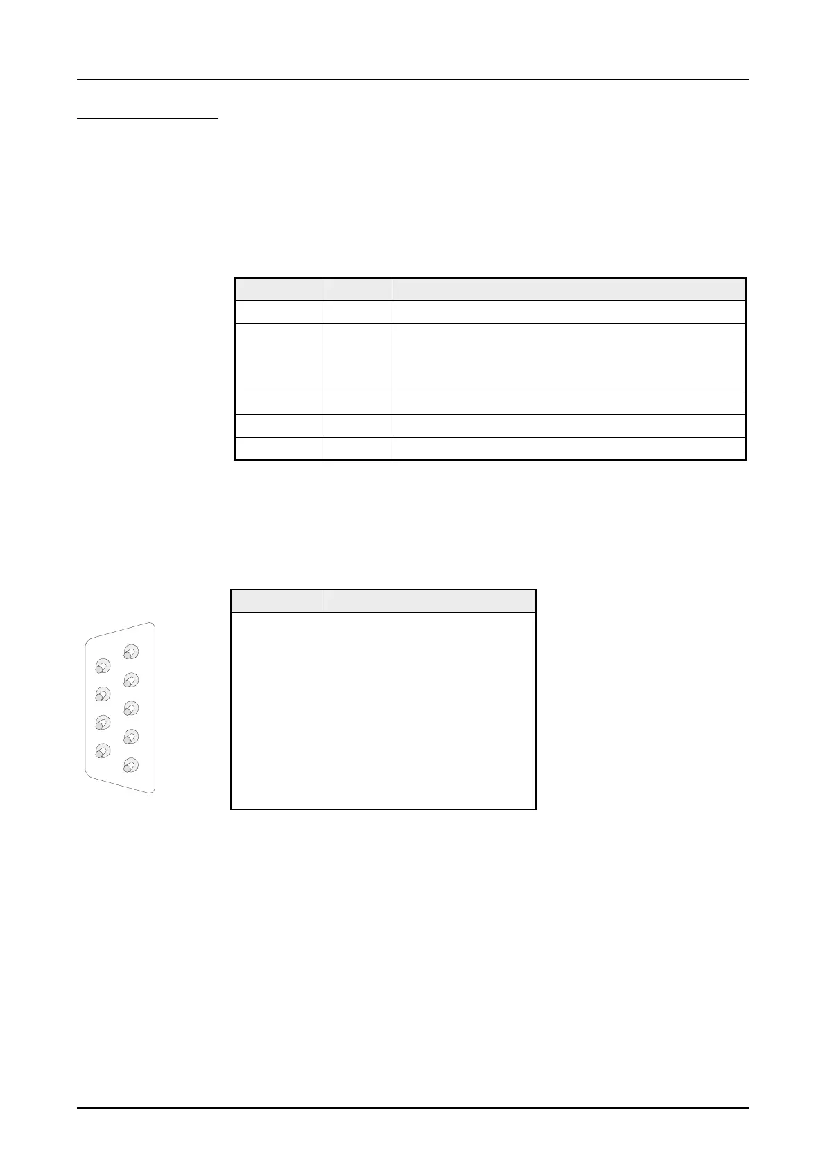
The CPU 21xSER-2 has got a communication processor with 2 RS232C
interfaces. The pin assignment of the interfaces is as follows:
9pin jack
Pin Assignment
1 CD-
2 RxD
3 TxD
4 DTR-
5 GND
6 DSR-
7 RTS-
8 CTS-
9 RI-
CPU 21xSER-2
LEDs
RS232C
interface
COM1, COM2
1
2
3
4
5
6
7
8
9