Installation
Connecting Power
VT200/220 Technical Manual, Rev 1.00.01 22 Doc # TM-VT200/220-EN
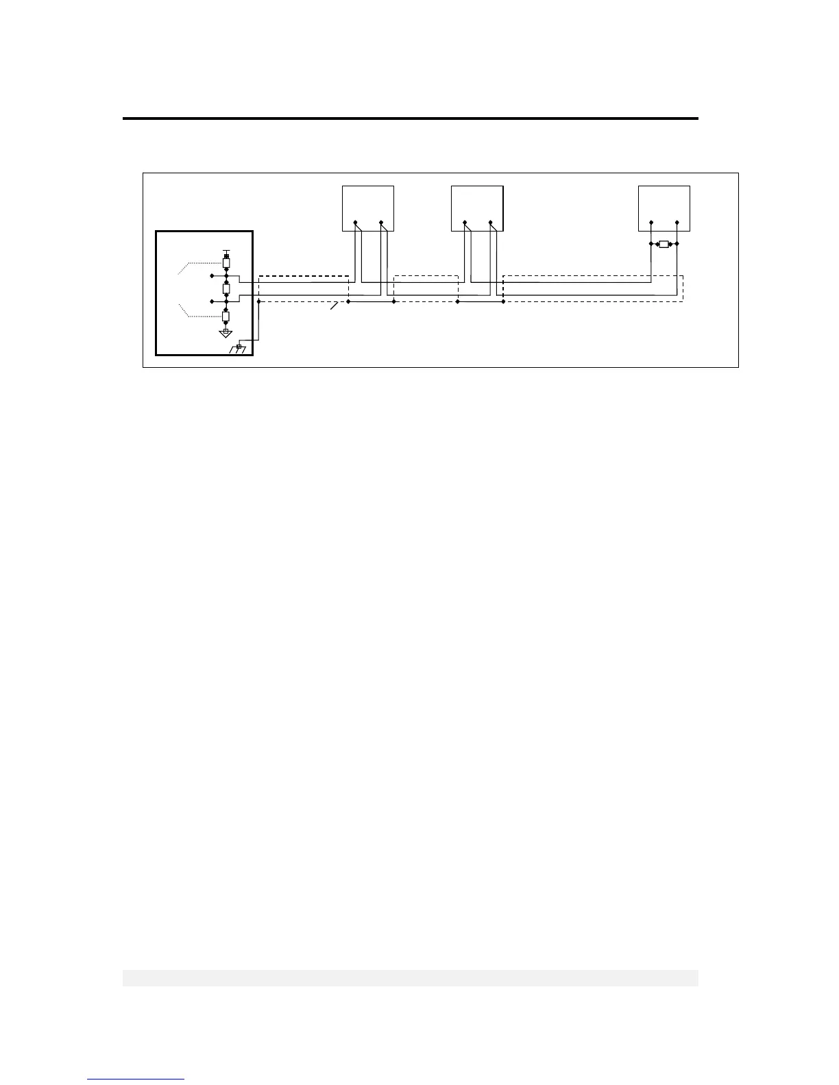
Figure 6 – RS485 cable connection diagram
2.5 Connecting Power
VT200/220 indicators are powered from 85-265 VAC, via internal power supply board.
The mains power cable is supplied with the instrument.
Power should be isolated from other data processing equipment.
Verify that the AC power socket outlet is properly protected. For optimum EMC
performance, keep the length of cable shielding inside the enclosure as short as
possible.
Chassis
Earth
470


 To Next Page