Do you have a question about the Vishay VT400 and is the answer not in the manual?
Covers safety symbols, general safety practices, and special warnings for safe operation.
Details on AC mains connection requirements and optimal operating environment conditions for the indicator.
Explains the document's style conventions for text, keys, menus, commands, and warnings.
Provides general technical specifications including CPU, communication, display, keyboard, and approvals.
Details on load cell excitation, signal range, sensitivity, amplifier, and A/D converter characteristics.
Specifications for the optional analog output, including power, current/voltage, resolution, and protection.
Specifies input voltage, resistance, and delays for digital inputs.
Details output voltage, current, delays, and protection for digital outputs.
Guidelines for selecting an appropriate mounting location for the indicator.
Instructions for panel mounting the indicator and general wiring guidelines.
Details on connecting load cells using shielded cable and diagrams for pin connections.
Explains load cell utilization ranges for excitation and gain/input.
Specifies cable types and requirements for RS232 and RS485 serial connections.
Diagrams and pinouts for connecting printers and PCs via serial cables.
Guidance on connecting the external power supply and ensuring proper grounding.
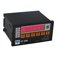
Description of the VT400's display layout and status annunciators.
Lists common messages displayed by the indicator and their meanings.
Overview of the six front panel keys and their dual functions.
Explains how to use the keys to perform operations like zeroing and taring.
Details on using keys for menu navigation and entering numeric values.
Procedure for editing multi-digit values displayed on the indicator.
Introduction to the function menu for advanced operations.
Step-by-step guide on how to access and use functions from the function menu.
Summary of available functions, their descriptions, and reference sections.
Overview of the setup menu system for configuring the indicator.
Procedure for entering and navigating the setup and calibration menus.
Diagram illustrating the main and submenu structure of the setup menus.
Lists parameters within the SETUP, PAR, CAL, STORE, INIT, and A-CAL menus.
Guide to calibrating the scale using standard weights (Zero and Span).
Step-by-step instructions for performing zero calibration using standard weights.
Step-by-step instructions for performing span calibration using standard weights.
Introduction to electronic calibration using mV values.
Example and method for calculating dead-load and span calibration values.
Procedure for electronically setting the zero calibration value.
Procedure for electronically setting the span calibration value.
Instructions for saving calibration data to permanent memory.
Procedure for sealing the indicator to prevent unauthorized access.
Details on applying non-removable and lead wire/plastic stickers for sealing.
Information on inscribing the load receptor serial number on the indicator label.
How to check the calibration seal status and audit trail counter using function 48.
Accessing and editing general system parameters in the PAR menu.
Procedure for accessing and editing parameters within the PAR menu.
List and description of parameters available in the PAR menu.
Overview of the SETUP 1 menu for totalizer and key locking functions.
Procedure for accessing and editing parameters within the SETUP 1 menu.
List and description of parameters available in the SETUP 1 menu.
Details on configuring serial ports 1 (RS232) and 2 (RS232/RS485).
Specifications and connection details for the RS232 serial port.
Specifications and connection details for the RS485 serial port.
Guide to setting output parameters for serial ports 1 and 2.
Defines the output type for serial port 1.
Defines the output type for serial port 2.
Lists and describes the different output types supported by the indicator.
Details on the local printer output format.
Information on continuous weight data transmission.
Details on the print on demand feature.
Information on transmitting alibi serial number and weight.
Describes commands available when alibi mode is active.
Details on the EDP protocol for host computer communication.
Information on transmitting local printer data to a remote printer.
Details on configuring the indicator for master-slave communication.
Overview of the indicator's output and digital input capabilities.
Technical specifications for the digital outputs (setpoints).
Technical specifications for the analog output channel.
Technical specifications for the digital input, used as a tilt switch.
Diagrams for connecting digital outputs and the tilt switch.
How to set upper and lower weight thresholds for digital setpoints.
Parameters for configuring setpoint outputs, including net/gross and logic.
Overview of configuring the analog output channel for PLC communication.
Instructions for connecting the analog output PCB and setting the output mode jumper.
Details on setting analog output parameters like span, mode, and error levels.
How to set the time delay for the tilt switch function.
Description of special options available for the tilt switch function.
Operations performed via the function menu, including password and seal checks.
Procedure for setting and changing the calibration password (PIN).
How to check calibration seal status and audit trail counter using function 48.
How to view the load cell mV output using function 80.
How to view the analog-to-digital converter count using function 81.
How to view the current software version number and release date.
Procedure for locking and unlocking front panel keys via setup menus.
Overview of diagnostic tests for the indicator's hardware and software.
How to test the integrity of the unit's ROM and RAM using function 86.
How to test the keypad and display functionality using functions 90 and 91.
How to test digital inputs and outputs (setpoints) using function 93.
How to test the print buffer using function 94.
How to test data reception on COM ports using function 96.
Table of error codes, possible causes, and recommended actions.
Steps to check load cell connections for proper functionality.
Troubleshooting steps for power supply issues if the unit does not turn on.
How to test digital inputs and outputs if setpoints are not working correctly.
A block diagram illustrating the system architecture and component interconnections.
Diagram showing rear panel connections for the desktop model.
Diagram showing terminal connections for the wall-mount model.
Illustrates cabling for RS485, digital outputs, tilt switch, and printer/PC connections.
Defines communication between a host computer (master) and weighing terminals (slaves).
Specifies baud rates, data bits, parity, and message structure for communication.
Details the format of nine-byte messages including ID, Command, Data, and BCS.
Describes the master-slave communication flow, including polling and response mechanisms.
Lists and describes the commands available for master-slave communication.
Command to poll slaves for weight and status information.
Command to reset a slave unit to its power-on state.
Command to upload the tare value from the scale.
Command to emulate keypad presses for remote control.
Command to download setpoint values to the slave.
Command to upload setpoint values from the slave.
Command to read the status of setpoint outputs.
Command to set or cancel setpoints without activating them.
Command to activate setpoints after forcing them.
Command to upload error codes detected by the slave.
Command to execute a specified function remotely.
Commands for downloading parameters for setup and calibration.
Describes the message formats for uploading setup parameters.
| Brand | Vishay |
|---|---|
| Model | VT400 |
| Category | Accessories |
| Language | English |