Installation
Connecting Load Cells
VT400 Technical Manual, Rev. A5 18 Doc # UM-VT400-EN
2.2.2 Wiring
All connections to the instrument are made through the rear panel connectors. Strain-
relief clamps should be used. The shield should be connected to the metal frame of
the connector.
Do not run signal cables together with power cables. Connect the shielding only
where indicated in the drawing. Never use a Megger to check wiring. Never use
plastic insulating tape on load cell connections.
2.3 Connecting Load Cells
Use 6 x 0.5mm
2
shielded cable for load cell connections. Maximum length 300m.
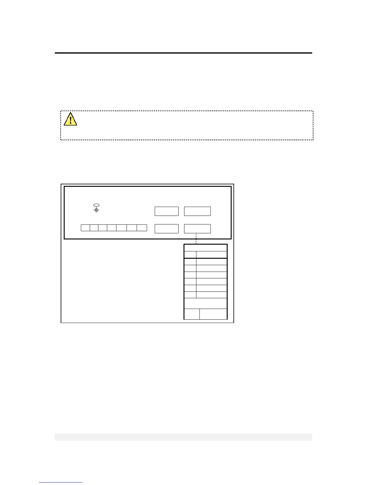
Connect the load cells according to the diagram below.
Figure 2 – Load cell connection diagram
1 2 3 4 5 6 7
+ - I
1
C
I
O
1
O
2
+C
o