Installation
Connecting Power
VT400 Technical Manual, Rev. A5 20 Doc # UM-VT400-EN
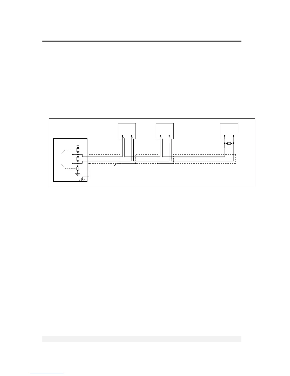
2.4.2 RS485 Cable Connections
The terminal block on the RS485 board enables connecting two pairs of wires (A, B):
One wire pair for connecting the incoming cable.
A second wire pair for a daisy-chain connection to the next unit on the RS485
bus.
The RS485 cabling configuration is illustrated in Figure 4 below.
Figure 4 – RS485 cable connection diagram
2.5 Connecting Power
VT400 indicators are powered from an external power supply (24VDC) or battery.
Power should be isolated from other data processing equipment.
Verify that the AC power socket outlet is properly protected. For optimum EMC
performance, keep the length of cable shielding inside the enclosure as short as
possible.
Network
Biasing
Resistors
Chassis
Earth
470R
150R
470R
A
B
RT
+V
White