Outputs and Digital Input
Configuring Analog Output
VT400 Technical Manual, Rev. A5 53 Doc # UM-VT400-EN
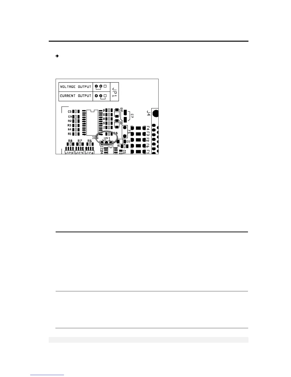
To set output mode jumper (JP1):
Set jumper JP1 to the appropriate position, to define voltage output or current
voltage, as shown in the image below.
7.4.2 Setting Analog Output Parameters
The output can be set to the standard calibration, where 0 on the weight display is
output as 0mA or 4mA, and max on the display is output as 20mA. The output is
capable of driving 20mA into 1K Oho load.
Alternatively, you can edit these zero and span calibration values. This is controlled
through the A.1 parameter, which, when set to 1, opens a dialog that allows you to
enter mA values for zero and span.
There are several other analog output parameters, detailed in the table below.
Par. Description Values
A.1 Standard / custom zero and span.
0 specifies that the scale should output 0mA at zero input and
20mA at maximum input (or 0V at zero and 10V at max).
1 opens a dialog, after A.8, that allows you to enter custom
zero and span values. Press PRINT to confirm; the display
shows 0 XX.XXX. Enter the D/A output at zero, in voltage or
mA, and press PRINT. The display shows F XX.XXXX. Enter the
D/A output at maximum input, in voltage or mA, and press
PRINT.
0 = Standard (20mA max)
1 = User defined Zero and
Span
A.2 Normal or absolute AOUT mode. Specifies what happens
when the displayed weight is negative: analog output is either
zero (normal mode) or the absolute value of the negative
reading (absolute mode). For example, if the display shows -
100.00, and absolute mode is set, AOUT=10mA. In normal
mode, AOUT=0mA, regardless of the negative reading.
0= Normal
1 = Absolute