Installation
Serial Connections
VT400 Technical Manual, Rev. A5 19 Doc # UM-VT400-EN
2.3.1 Load Cell Operating Parameters
The load cell utilization ranges are listed in the table below.
Excitation 5VDC, fixed or alternating polarity (setup-selectable) for 10 load cells of 350Ω
each.
Gain / input ranges • For load cell output of 10mV, gain permitted is between -0.25 and 1.75mV/V.
• For load cell output of 20mV, gain permitted is between -0.25 and 3.75mV/V.
The load cells must be chosen so that the input signal to the controller is at least
0.4µV per scale increment. For load cell output less than 0.4µV/digit, the
controller will still be stable but the full temperature range accuracy is not
guaranteed.
2.4 Serial Connections
For RS232C connection, use 3 x 0.34mm
2
shielded cable.
For RS485 connection, use 2 x 0.34mm
2
shielded twisted pair cable.
2.4.1 Printer and PC Cables
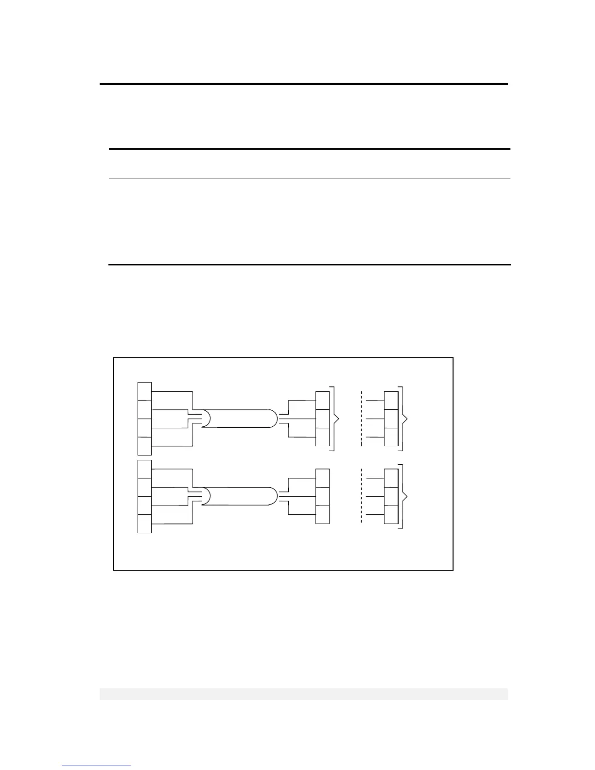
Figure 3 – Printer and PC cables connection diagram
RX
Max 15m
Max 15m
To
PC
To
Epson
Printer
DB9
Metal
Case
3
5
2
3
5
2
DB9
fem
DB9
Metal
Case
DB9
fem
Shield
TX GRN
GND BRN
DTR WHI
Shield
TX GRN
GND BRN
DTR WHI
GRN RX
BRN GND
WHI
DTR
GRN RX
BRN GND
WHI
DTR
RX
GND