Outputs and Digital Input
Configuring Analog Output
VT400 Technical Manual, Rev. A5 52 Doc # UM-VT400-EN
7.4 Configuring Analog Output
The analog output channel allows the indicator to communicate with PLC devices,
using one of the following two methods:
Converting load cell input into voltage (0-10V)
Converting load cell input into current (0-20mA or 4-20mA)
This feature is only active if your indicator is equipped with an optional analog output
board. Section 7.4.1 below explains how to connect the analog output board, and set
a hardware jumper to define which of the two output methods to use.
After connecting the board and setting the jumper, you can set analog output
parameters using the SETUP > A-CAL menu (see section 7.4.2).
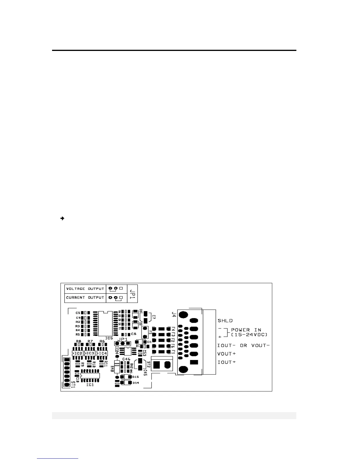
7.4.1 Connecting PCB and Setting Jumper
In order to use analog output, the option PCB (PCB 761) must be connected to the
VT400 as follows: To ST5 socket in the one side and to the rear panel in the other
side, using the mounting posts/spacers provided.
Jumper JP1 determines the output mode – current or voltage.
Analog output pins connections:
1. Connect pins as follows:
For current output, connect pin 1 (current output, +) and pin 3 (common).
For voltage output, connect pin 2 (voltage output, +) and pin 3 (common).
2. Connect an external power supply of 24VDC, using pins 4 and 5:
Pin 4 – power in (+).
Pin 5 – power in (-).