VT5500 INSTALLATION GUIDE
10
t +44 (0) 1246 225 745 | e orders@visiontrack.com | w visiontrack.com
Power Supply:
The power connection for the VT5500 is simple, it consists of three wires and
connections:
• Permanent Power (12/24V)
• Ignition ACC
• Ground
NOTE: Always test the wires with multimeter prior to making the connections.
NOTE: Turn off the ignition and remove the key prior
to making any connections.
• Connect the black wire to a suitable ground
• Connect the red wire to permanent 12 or 24V power
• Connect the yellow wire to a 12 or 24V ignition feed
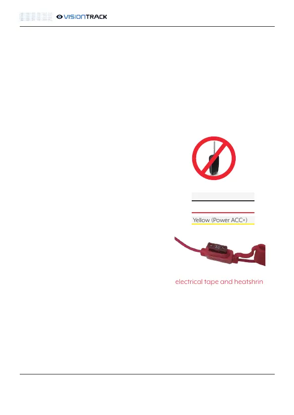
NOTE: You need to ensure that the 7.5A fuse
is in the fuseholder for the permanent power.
NOTE: All solder joints must be insulated with both electrical tape and heatshrink /
amalgamating tape to comply with Masternaut Standards. Please press here for
details.
NOTE: The fuse for the ignition connection is built into the DVR unit itself.
Black (Ground)
Red (Power Battery+)
Yellow (Power ACC+)
 Loading...