VT5500 INSTALLATION GUIDE
15
Cable Routing:
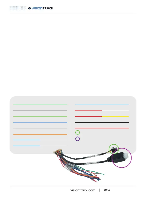
Alarm In/Out Cable - Wiring Diagram:
t +44 (0) 1246 225 745 | e orders@visiontrack.com | w visiontrack.com
When routing the VT5500G and camera cables you must ensure that you do the following:
• Secure the cables with cable ties at regular intervals
• Avoid blocking or interfering with airbags or moving parts
• Follow existing wiring where possible
• Use conduit for cables routed on the outside of the vehicle
NOTE: More information on how and where to route camera cables can be found in the specific
camera guides.
Green (Sensor In 1)
Grey (Sensor In 2)
Light Green (Sensor In 3)
Light Blue (Sensor In 4)
Grey (Sensor In 5)
Orange (Sensor In 6)
Blue/Black (Sensor In 5)
Blue/White (Sensor In 6)
Blue (Speed In)
Red/White (Sensor Out 1)
Red/Yellow (Sensor Out 2)
Black (Ground)
Red (+5V)
VT-CP4 / RS232-RS485 Convertor
MIC (Voip and dial in accessory)
NOTE: All Sensor In wires are voltage on/off (5-12V).
 Loading...