Do you have a question about the Vislink AFD120 X and is the answer not in the manual?
Highlights labels for hazardous AC voltages present on the equipment.
Identifies potential radiation hazard at waveguide connections and antennas.
Advises caution when moving items exceeding 25kg; requires assistance.
Warns against touching moving parts during antenna operation.
Warns of hazardous voltages and capacitor discharge during testing.
Illustrates microwave energy containment and power density limits.
Ensures antenna is stowed when vehicle is in motion to prevent damage.
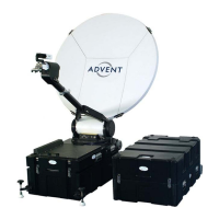
Details system capabilities, satellite bands, flyaway/roof rack use, and packaging.
Covers type, diameter, configuration, mount, frequency, and gain (dBi).
Details VSWR ratios, port isolation, and waveguide flange types.
Specifies feed type, optional ports, and RF power output.
Details antenna limits, display resolution, power, and consumption.
Covers azimuth, elevation, polarization adjustments, speeds, dimensions, and weight.
Details operational parameters for temperature, humidity, wind, and vibration.
Step-by-step guide for assembling the antenna in flyaway configuration.
Completes flyaway assembly steps, including polarization and segment fitting.
Instructions for mounting the antenna onto a vehicle's roof rack.
Details HPA mounting, waveguide connection, and roof rack foot removal.
Guidance on manually moving antenna axes when control circuits fail.
Describes two stowage configurations: sub 32kg for air travel and quick deployment.
Explains how to adjust the feedhorn for polarization modification.
Details the DCU5000 for motorised control, stow/deploy sequencing, and stow positions.
Emphasizes disconnecting power before performing any maintenance.
Covers inspection of dish, gears, drives, cables, feedhorn window, and waveguide.
Provides torque settings for screws/bolts and outlines radiation check procedure.
Covers warranty period, limitations, exclusions, and claims for damage/service.
Details procedures for returning products, packaging, and evaluation authorization.
Covers customer and shipping agency responsibility for returned product condition.
Illustrates Flydrive 120 standard and roof rack configurations with dimensions.
Shows Flydrive 150 flyaway and roof rack configurations with dimensions.
Depicts Flydrive 150 stowed antenna and satellite geometry diagrams.
| Gain | 12 dBi |
|---|---|
| Wind Survival | 200 km/h |
| Connector Type | N-Type Female |
| VSWR | < 1.5:1 |
| Impedance | 50 Ω |