3.3.3 Status–Monitor Radio
The Monitor Radio screen displays the following information.
+12V Displays the +12V system voltage in the DXL8000.
+5V Displays the +5V system voltage in the DXL8000.
System Temp
Displays the degrees in centigrade of the DXL8000 IDU operating temperature.
Test Tone
Available only with an internal SCM, displays On or Off.
Front Panel Display
You can choose to display the transmit (TX Power Only) or receive (RSL Only) status on
the front panel of the DXL8000. You can also display both transmit and receive status
(Cycle Values) for a specified number of seconds each.
3.3.4 Status–Firmware Revisions
The Firmware Revision screen displays identifying information for the DXL8000. Have this
information ready when you call for customer service as described in Section 1.3, About the
Outdoor Unit.
System Software
SCM PC FPGA (single carrier modulator PC field programmable gate array)
SCM PC uP (single carrier modulator PC microprocessor)
SCD PC FPGA (single carrier demodulator PC field programmable gate array)
SCD PC uP (single carrier demodulator PC microprocessor)
Radio Type
3.3.5 Status–Monitor Mod
The Monitor Mod screen displays the following information.
Symbol Rate
Displays 3.0 to 33 mega-symbols per second (Msps).
Modulation
Displays the modulation type (QPSK, 16QAM, 32QAM, 64QAM).
Note: 64QAM is limited to 20 Msps and above.
Percent Utilization
If this number is over 98%, you should adjust the values described in Section 3.4.6,
Determining Overall System Capacity Versus Bandwidth and Section 3.4.7, Determining
Optimal Data Rate Versus Error Correction.
Core Channel
1, 2, 3, and 4
Displays one of the following data inputs and its speed at megabits per second
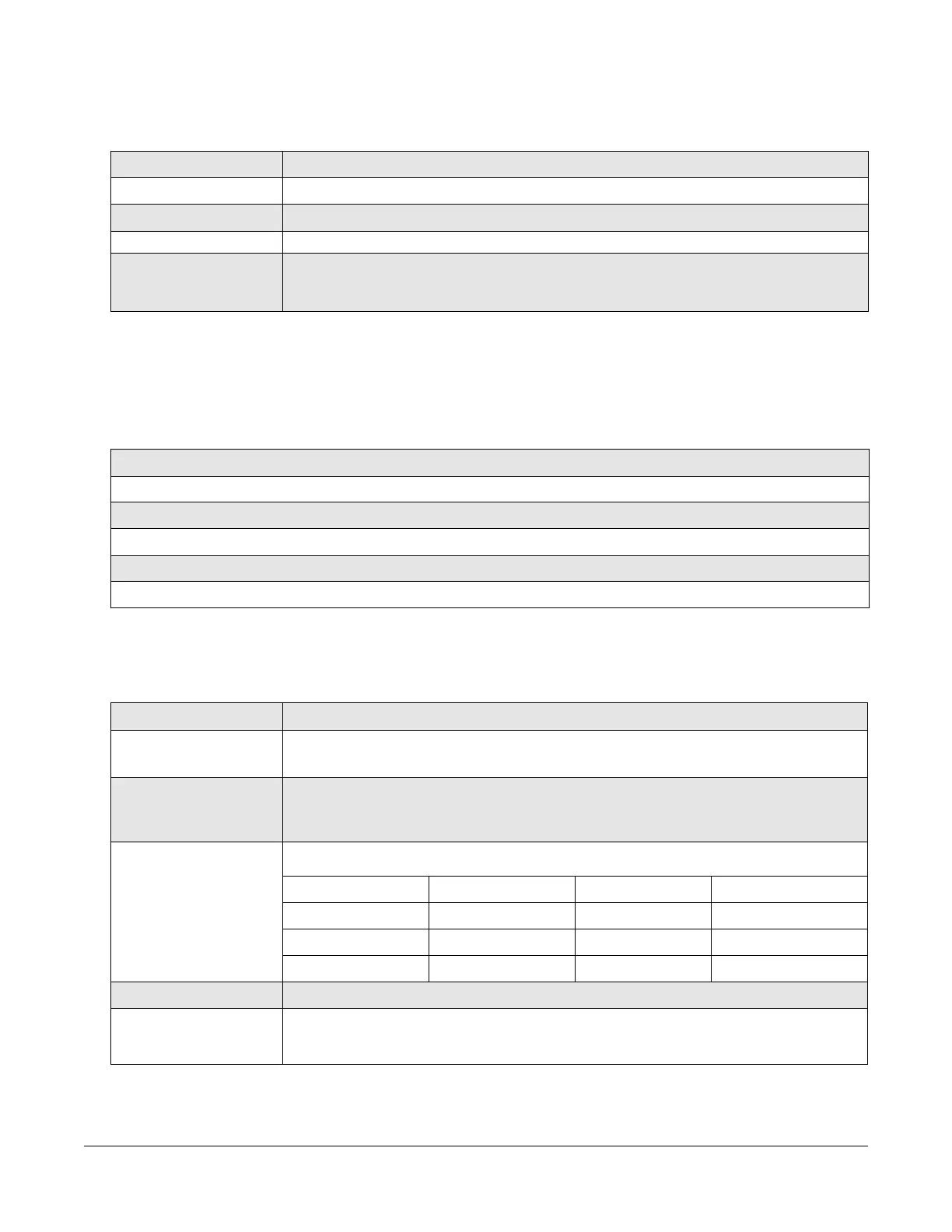
ASI BNC-1 DS3 BNC-1 E1RJ45-1 Ethernet RJ45-1
ASI BNC-2 DS3 BNC-2 E1RJ45-2 RS232
ASI BNC-3 DS3 BNC-3 T1RJ45-1 RS485
E3 BNC-1 E3 BNC-2 T1RJ45-2 SMPTE BNC-3
Invert Spectrum
Displays On or Off for the Invert Spectrum.
PRBS
Displays On or Off for the Pseudo Random Bit Sequence (PRBS). Note that one side must
be inverted, Modulated or Demodulated.
DXL8000 User and Technical Manual
Operating the DXL8000 3-3
 Loading...