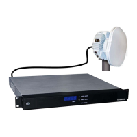
A.5 T1/E1 CHAN1 and CHAN2 Connectors
The following table shows the pinouts for the T1/E1 CHAN1 and T1/E1 CHAN2 RJ-45
connectors that provide Channel 1 and Channel 2 T1/E1 inputs to the unit.
Connector Pin CHAN1 Signal CHAN2 Signal
1 2 3 4 5 6 7 8
1
RX, Ring, – RX, Ring, –
3
Shield/Ground Shield/Ground
4
TX, Ring, – TX, Ring, –
5
TX, Tip, + TX, Tip, +
6
N/C N/C
7
N/C N/C
8
N/C N/C
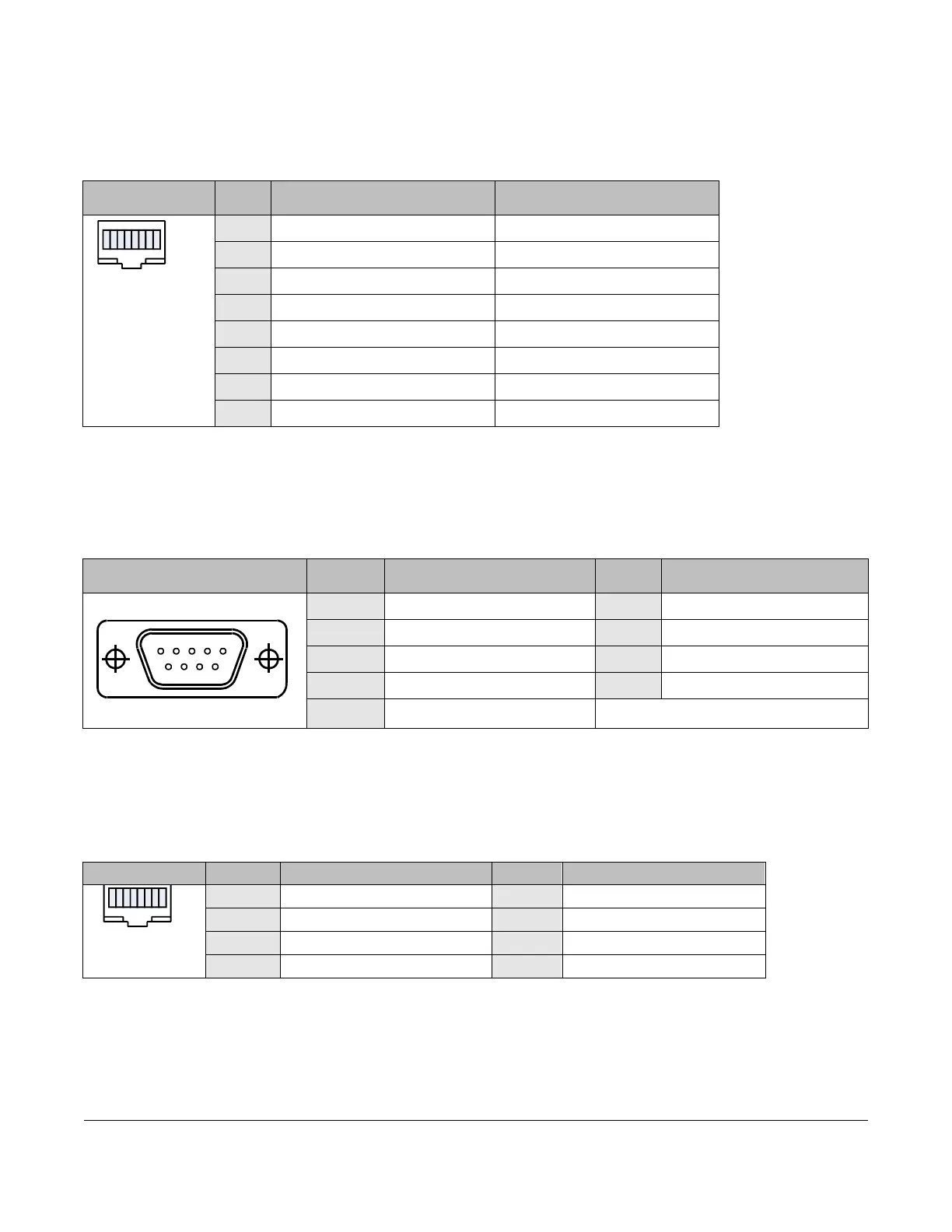
A.6 WAYSIDE DATA Connectors
The following table shows the pinouts for the Wayside channel, which is a simplex data channel
transmitting data from the DXL8000 Transmitter to a receiver system.
Connector Pin Signal Pin Signal
1
5
6
9
1
NC
6
N/C
2
UART_TX
7
RS-485 Signal –
3
UART_RX
8
RS-485 Signal +
4
N/C
9
N/C
5
N/C
A.7 10/100 Connectors
The following table shows the pinouts for the 10/100 RJ-45 connector that provides 10/100
Base
T Ethernet connections to the unit.
Connector Pin Signal Pin Signal
1 2 3 4 5 6 7 8
1
TX+
5
N/C
3
RX+
7
N/C
4
N/C
8
N/C
A-2 DXL8000 Specifications DXL8000 User and Technical Manual
 Loading...