4 D-303372 TOWER-30AM PG2, TOWER-30AM K9-90 PG2 Installation Instructions
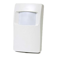
5. Insert battery while observing polarity.
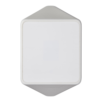
D. Enroll button (use a screwdriver to press the recessed button)
E. Battery
F. Tamper switch
CAUTION! THE BACK TAMPER SWITCH WILL NOT PROTECT THE UNIT UNLESS THE BREAK-AWAY BASE SEGMENT IS
SECURED TO THE WALL WITH AT LEAST ONE SCREW.
CAUTION! RISK OF EXPLOSION IF BATTERY IS REPLACED BY AN INCORRECT TYPE. DISPOSE OF USED BATTERY
ACCORDING TO MANUFACTURER'S INSTRUCTIONS.
Note: Back Tamper must be enabled for UL installations.
Figure 3. Mounting
2.3. Enrollment
Refer to the PowerMaster control panel's Installer Guide and follow the procedure under the "02:ZONES/DEVICES" option of the
Installer Menu. A general description of the procedure is provided in the following flow chart.
Enter the Installer menu
and select
“02:ZONES/DEVICES”
Select "ADD NEW
DEVICE" Option
See Note [1]
Enroll the device or Enter
the device ID
Select the desired Zone
Number
Configure
Location, Zone
Type & Chime
Parameters
means scroll and select
Notes:
[1] If the detector is already enrolled you can configure the detector parameters via the “Modify Devices” option – see Step 2.
[2] Select the "Device Settings" option and refer to section 2.4 to configure the detector parameters.
2.4. Configuring the Detector Parameters
Enter the menu and follow the configuration instructions for the TOWER-30AM PG2 PIR detector as described in
the following table.
Configuration Instructions
Define whether or not the alarm LED indication will be activated.
Optional settings: LED ON (default) and LED OFF.
Define whether an alarm will be activated upon continued motion (low sensitivity) or upon a single alarm event
(high sensitivity).
Optional settings: LOW sensitive (default) and HIGH sensitive.
Define whether or not to set the activity time during disarm.
Optional settings: NOT Active (default), YES – no delay, YES + 5s delay, YES + 15s delay, YES + 30s delay,
YES + 1m delay, YES + 2m delay, YES + 5m delay, YES + 10m delay, YES + 20m delay and YES + 60m
delay.
Define the activity and the sensitivity level of the anti-masking.
Optional settings: LOW sensitive (default), HIGH sensitive and disabled.
3. LOCAL DIAGNOSTICS TEST
NOTE: Run a diagnostic test at least once a year to ensure that the detector is working correctly.
A. Separate the base from the cover (see Fig. 3).
 Loading...