3. POWERMASTER-10 G2 INSTALLATION
12
D-304762 PowerMaster-10/30 G2 Installer's Guide
3.6 Adding Wired Zones or PGM Device
Required tools: Cutter and slotted screwdriver - 3 mm blade.
PowerMaster-10 G2 wiring is shown in Figures 3.6a – 3.7b.
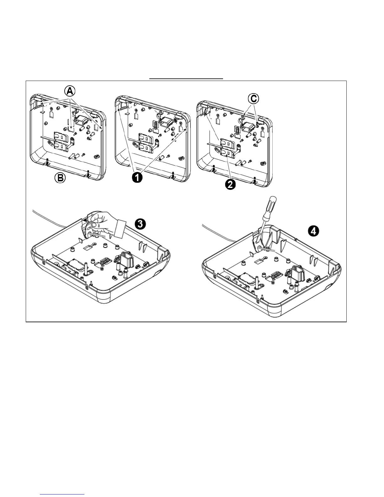
CABLES ROUTING GUIDE
A. Cables entry options
B. Back unit
C. Cable clips
To Route the Cable:
1. Remove the left or
right side cables
entry knockout(s)
and enter the
required cable(s)
2. Remove and use as
cable clamp(s)
To Route the Cable (continued):
3. Position the clamp (1 of 2) as shown and then rotate into place.
4. Using a slotted screwdriver press downward gently on the point illustrated in the drawing. Make sure the clamp is
locked (a click is heard).
Figure 3.6a – Cable Wiring
 Loading...