4. POWERMASTER-30 G2 INSTALLATION
D-304762 PowerMaster-10/30 G2 Installer's Guide
17
4. POWERMASTER-30 G2 INSTALLATION
Required tool: Philips screwdriver #2.
PowerMaster-30 G2 mounting process is shown in Figures 4.1 - 4.13.
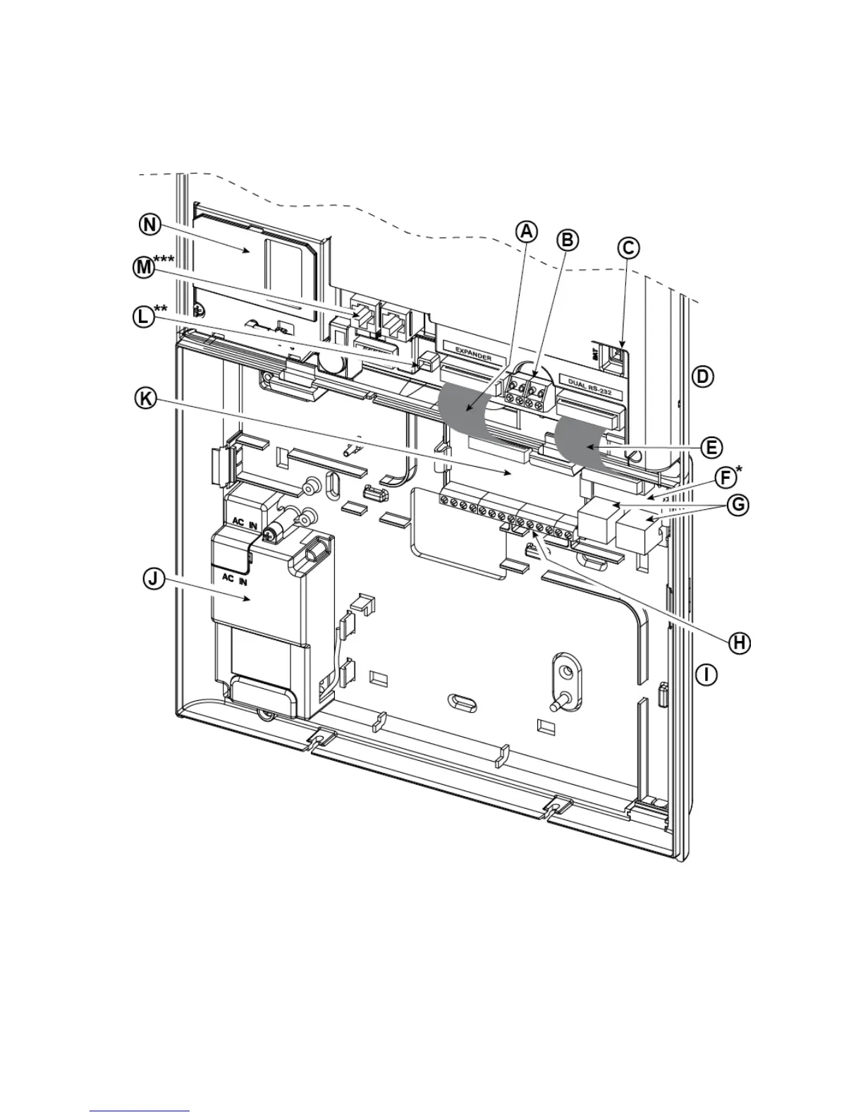
4.1 PowerMaster-30 G2 Wiring Diagram
A. Expander Module Flat
Cable
B. Wired Zone / Special
Siren Terminal Block
C. Battery Connector D. Front Unit
E. Dual RS-232 Module Flat
Cable
F. Dual RS-232 Module G. Dual RS-232 Module
Connectors
H. Expander Module Wiring
Terminal Blocks
I. Back Unit J. Power Supply K. Expander Module L. Power Connector
M. Phone Wiring
Connectors
N. GSM-350 PG2
* or PGM-5 Module
** or External Power Connector
*** or Terminal Block in North American Panels
Figure 4.1 – PowerMaster-30 G2 Wiring Diagram
 Loading...