42
Vitrek 944i Calibration Procedure No. 944CP-052902
In order to maintain the accuracy specifications of the 944i, it is necessary to verify/calibrate the unit against external
standards on a periodic basis. Vitrek recommends a calibration interval of one year. A calibration seal/sticker may be
placed over the cal enable hole in order to prevent unauthorized access to the external calibration routine.
Note: Allow a 60 minute, power on, warm-up period at ambient temperature (within 5°C from calibration temperature).
Prior to conducting the following verification procedure, run a system test on the 944i including the output system check.
Should any errors be detected, consult your Vitrek service center. In the event that the unit fails to perform within the
given uncertainty levels, an external calibration to local standards may be required.
1. Calibration Verification
1.1. Voltage Output Accuracy
Connect a calibrated Vitrek 4600A Digital High Voltage Meter (or equivalent) to the V HI and V LO terminals of the
944i. Select the VDC direct mode, and record the values for the tests indicated on the proper Calibration Sheet at the end
of this section.
Once completed with the VDC tests, select the VAC direct mode, and run the tests specified on the Calibration Sheet at
the end of this section.
1.2. Current Measurement Accuracy
First, connect the V HI terminal to a Vitrek 4610A Precision High Voltage Resistance Standard (or equivalent), and the
V LO terminal to the Common terminal. Select the VDC direct mode on the 944i and engage the output, but leave the
unit running at 100 VDC. Select the proper resistor and connect it to the 944i (see table below). Edit the voltage up to
1kv, and take your readings. Then, reduce the voltage back to 100 VDC and select the next resistor. Make sure to take
the unit back down to 100 VDC when switching resistors.
Run the four tests as specified on the 944i Calibration Sheet at the end of this section.
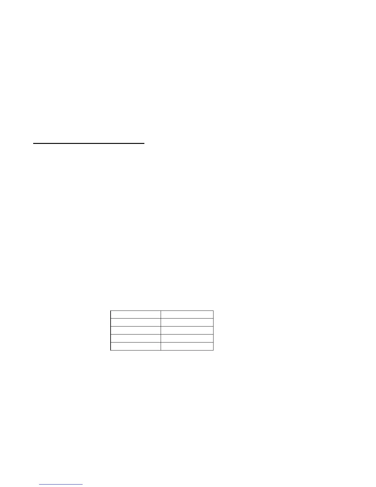
For your reference, this table shows which resistor is needed to create the necessary current (at 1000 volts)
Current Resistor
1000nA
1GΩ
10µA
100 MΩ
1mA
1 MΩ
10mA
100 KΩ
The same process applies for the VAC, except that the 1000nA current test does not need to be run, leaving only the
10µA, 1mA, and 10mA tests.
1.3. Meg-ohm Mode.
The meg-ohm function of the 944i is derived using the output voltage and corresponding leakage current. No
additional verification is required.