VIVOTEK
User's Manual - 11
Network Deployment
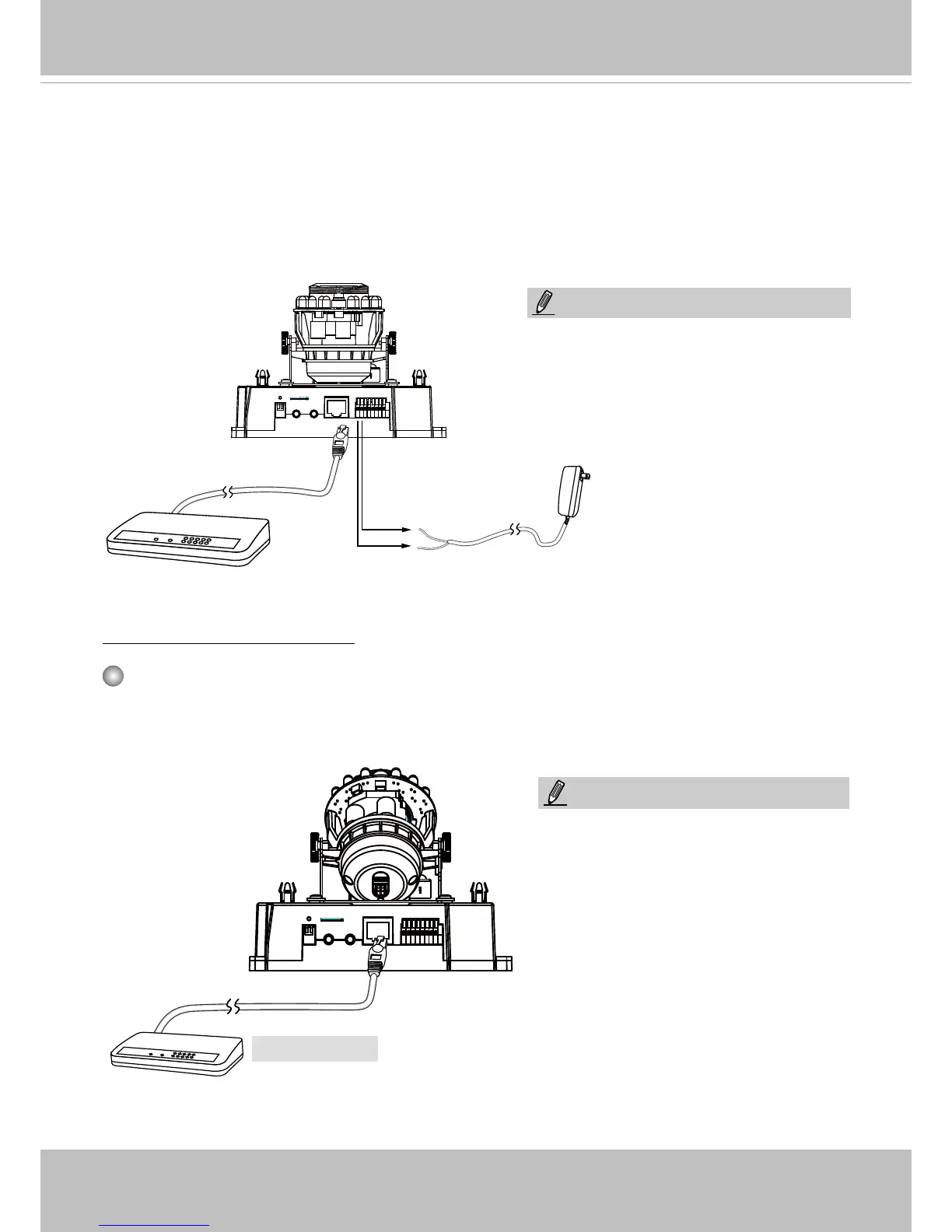
General Connection (without PoE)
Power over Ethernet (PoE)
POW
ER
C
OLL
I
S
ION
L
I
N
K
RE
CEIVE
PARTITIO
N
1
2
3
4
5
PoE Switch
When using a PoE-enabled switch
The Network Camera is PoE-compliant, allowing transmission of power and data via a sin-
gle Ethernet cable� Follow the below illustration to connect the Network Camera to a PoE-
enabled switch via Ethernet cable�
POW
ER
C
OLL
I
S
ION
L
I
N
K
RE
CEIVE
PARTITIO
N
1
2
3
4
5
1� If you have external DI devices, make the connection from general I/O terminal block�
2� Ethernet, power, and other cables are user-supplied�
3� Connect the AC cables from the terminal block as an alternate power source� The IO cables
are user-supplied�
Ethernet
Switch
Pin1 & 2 AC 24V
Pin #1 & 2 AC 24V as alternate power
are for indoor use only
NOTE:
1� This equipment is only to be
connected to PoE networks without
routing to outside plants�
2� For PoE input connections, use only
UL listed I�T�E� with PoE output�
NOTE: