VIVOTEK
14 - User's Manual
Internet connection with static IP
Choose this connection type if you are required to use a static IP for the Network Camera.
Please refer to LAN conguration on page 58 for details.
Internet connection via PPPoE (Point-to-Point over Ethernet)
Choose this connection type if you are connected to the Internet via a DSL Line. Please refer to
PPPoE on page 49 for details.
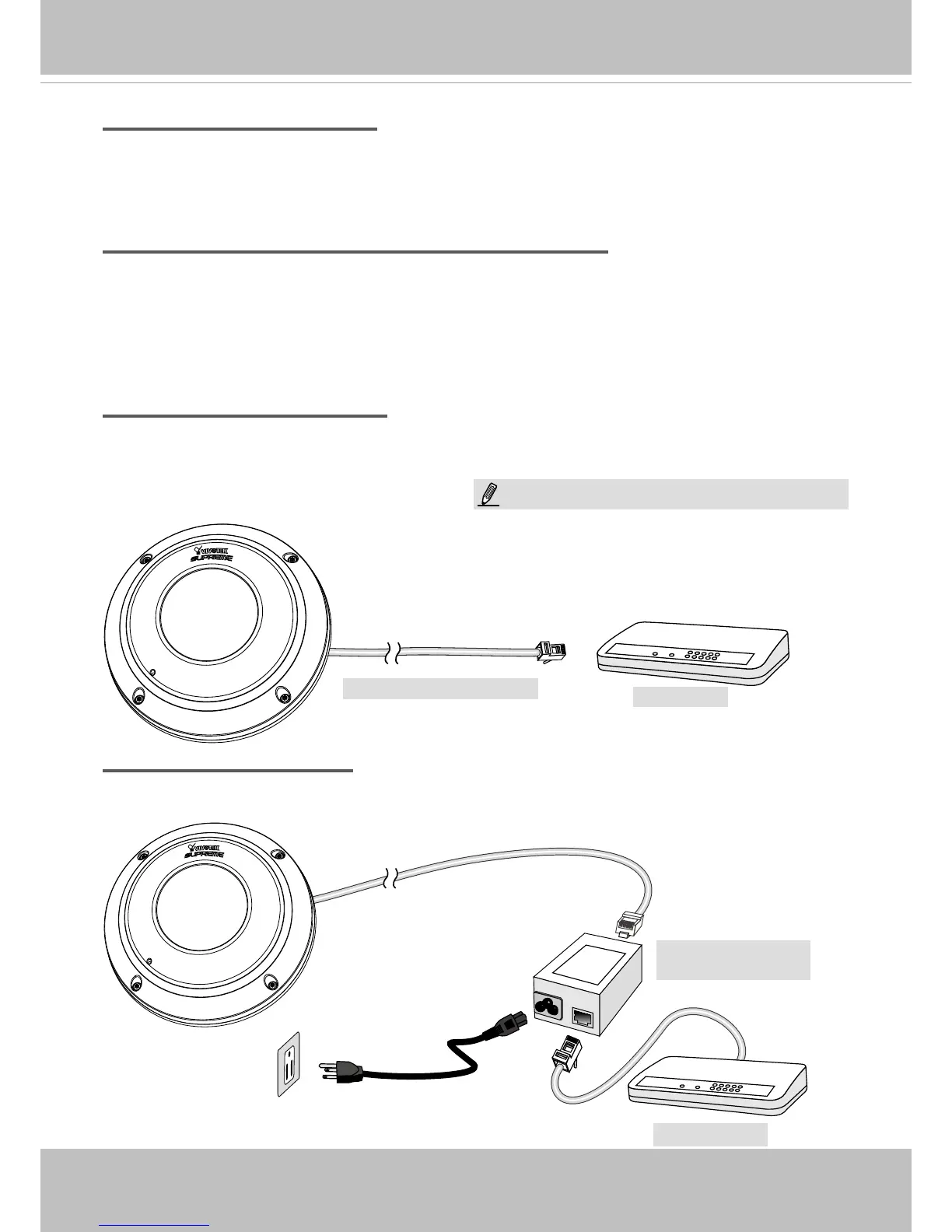
Set up the Network Camera through Power over Ethernet (PoE)
When using a PoE-enabled switch
The Network Camera is PoE-compliant, allowing transmission of power and data via a single
Ethernet cable. Follow the below illustration to connect the Network Camera to a PoE-enabled
switch via an Ethernet cable.
When using a non-PoE switch
If your switch/router does not support PoE, use a PoE power injector (optional) to connect
between the Network Camera and a non-PoE switch.
POW
ER
C
O
LL
I
S
ION
L
I
N
K
RECEIVE
PARTITIO
N
1
2
3
4
5
PoE Switch
Power + Data Transmission
POW
ER
C
O
LL
I
S
ION
L
I
N
K
RECEIVE
PARTITIO
N
1
2
3
4
5
Non-PoE Switch
PoE Power Injector
(optional)
NOTE:
1. The camera is only to be connected to PoE networks
without routing to outside plants.
2. For PoE connection, use only UL listed I.T.E. with PoE
output.