VIVOTEK
User's Manual - 15
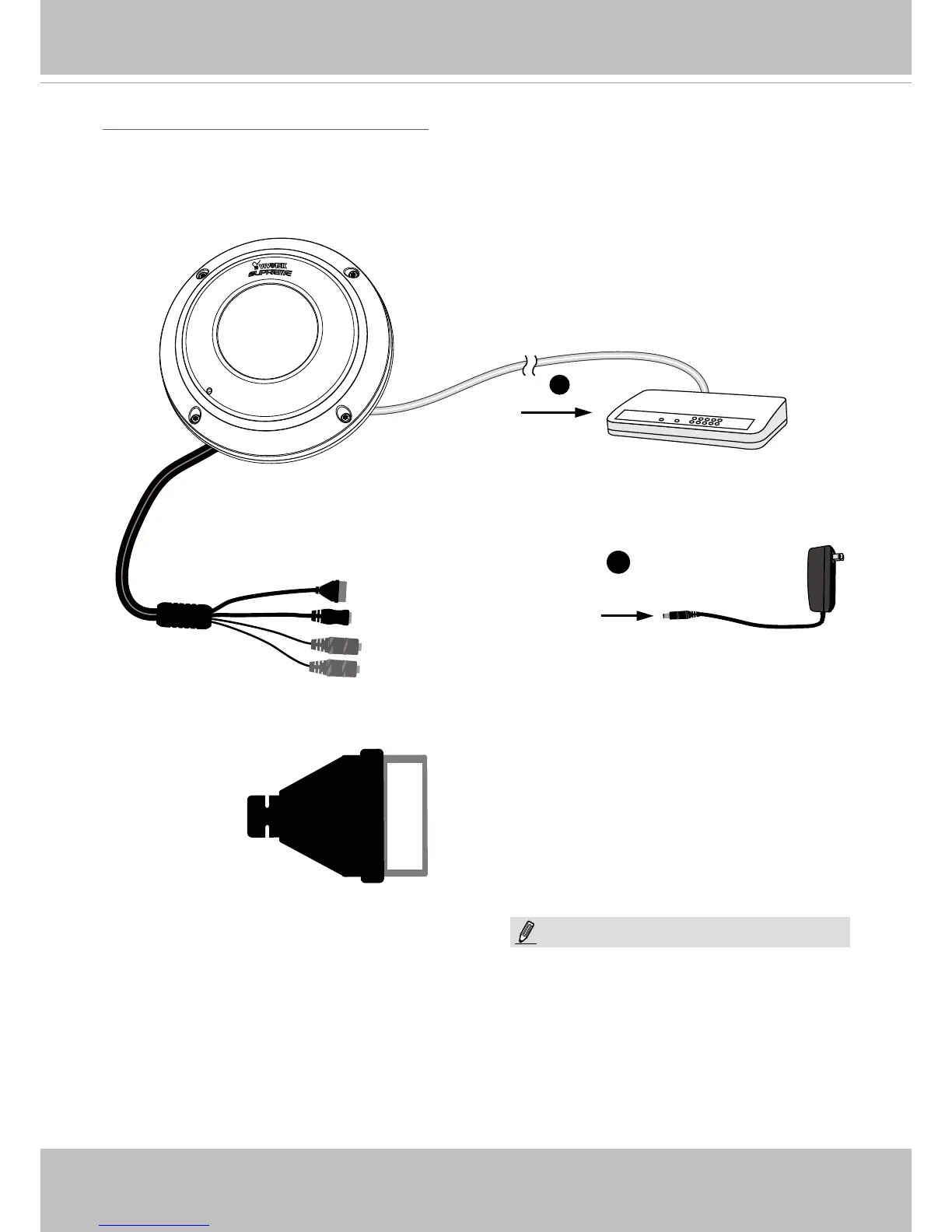
General Connection (without PoE)
+3V3
DO
DI
GND
POW
ER
C
O
LL
I
S
ION
L
I
N
K
RECEIVE
PARTITIO
N
1
2
3
4
5
1. If you have external DI devices, make the connection from general I/O terminal block.
2. Ethernet, power and IO cables are user-supplied. Use a Category 5 Cross Cable when
Network Camera is directly connected to PC.
3. Connect DC power cord to a DC Adapter, and then to a power outlet.
Ethernet
Switch
1
2
General I/O Terminal Block
Power Cord Socket (Black)
Microphone In (Pink)
Audio Out (Green)
+3V3 : Power, 3.3V DC
D O : Digital Output
D I : Digital Input
G N D : Ground
NOTE:
The power adapter should comply with L.P.S.
regulations featuring O/P: 12V DC, 1.5A min.