9
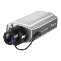
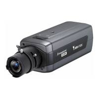
Network Camera provides a general I/O terminal block with one digital input and one
relay switch for device control. Pin 1 and pin 2 can be connected to an external sensor
and the state of voltage will be monitored from the initial state 'LOW'. The relay switch
of pin 3 and pin 4 can be used to turn on or off the external device.
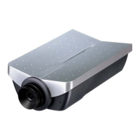
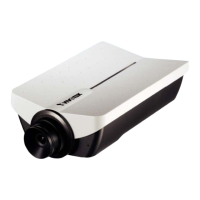
Power cord socket
Connect the power jack of the included power adapter. Connecting the power adapter
should be the last operation while physically installing Network Camera.