VIVOTEK - A Leading Provider of Multimedia Communication Solutions
4 - User's Manual
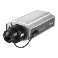
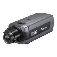
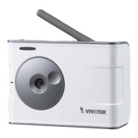
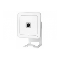
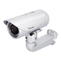
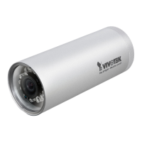
Physical Description
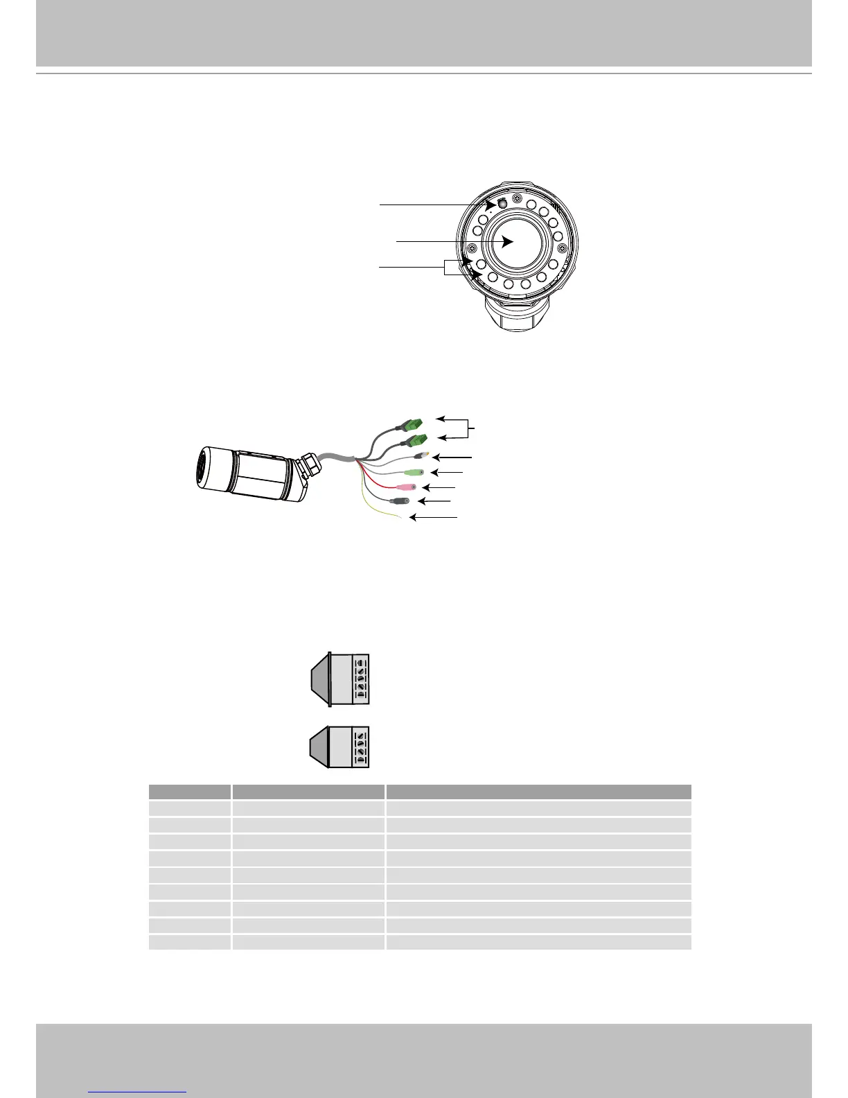
Front panel
Connectors
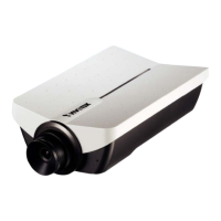
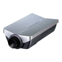
General I/O Terminal Block
This Network Camera provides a general I/O terminal block which is used to connect external
input / output devices. The pin denitions are described below.
IR LED
Lens
Light Sensor
Ethernet 10/100 RJ45 Plug
Audio Out (green)
Microphone In (pink)
Power Cord Socket (black)
General I/O Terminal Block
Earth
N�C�: No Connector
485B: RS485-
485A: RS485+
AC24V: Power in AC 24V
AC24V: Power in AC 24V
GND: Ground
DI : Digital Input
DO : Digital Output
+12V : Power, 12V DC
Pin Name Specification
N�C� No Connector
485B RS485- 3�3V
485A RS485+ 3�3V
AC24V Power in AC 24V AC 24V ± 5%
AC24V Power in AC 24V AC 24V ± 5%
GND Ground
DI Digital Iutput OPEN/Short-to-GND, isolation 2kV
DO Digital Output Max. 40VDC, max. 400mA, isolation 2kV
+12V Power +12V 12VDC ± 10%, max. 0.4A