VIVOTEK
14 - User's Manual
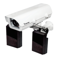
13. Prepare two power lines as the 24V inputs for the camera. Connect the input lines from
the enclosure's terminal to that on the camera. Also connect the DO- (black) and the
DO+ (red) lines from the IR unit to the camera's terminal connector. You only need to
connect one pair of LED ON/OFF mode DI wires to the camera.
DO+
DO-
DI1+
DI2+
DI3+
DI-
RS485-
RS485+
AC/DC pwr
AC/DC pwr
The LED ON/OFF mode DI connection enables the synchronization of IR light and the
automated day/night switching mechanism on the camera.
Listed below is the color scheme for wires coming fom the IR light units.
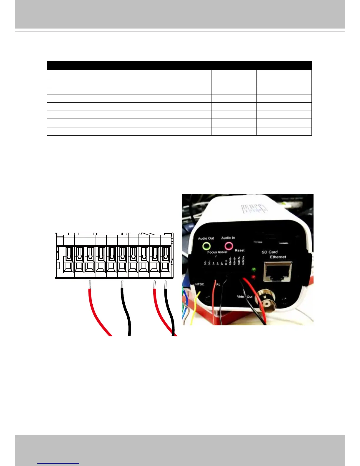
Description Color Gauge
IR status DO- Orange (26AWG)
IR status DO+ Brown (26AWG)
LED ON/OFF mode DO- Black (26AWG)
LED ON/OFF mode DO+ Red (26AWG)
Input(V-): 24V AC/DC or 12V DC Orange (20AWG)
Input(V+): 24V AC/DC or 12V DC Brown (20AWG)
Output(V-): Volts same as input Black (20AWG)
Output(V+): Volts same as input Red (20AWG)