VIVOTEK - Built with Reliability
20 - User's Manual
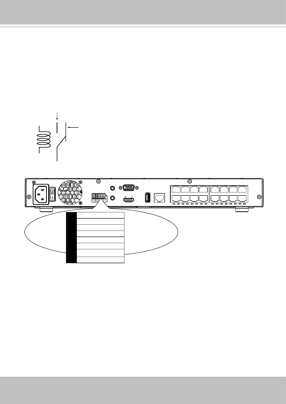
Terminal Block Connections
The terminal block pinouts is shown as follows:
The relay pins default status is set to Normally Open. Connect your relay or external devices’
signal wires to the system, the system will automatically detect the current signal status. You
can then trigger the external devices using the DI/DO panel on the live view.
You can also congure the system alarm setting for the system to automatically trigger a relay
pin on the occurrence of system events. See Alarm settings on page 101.
ssss
Normally Open
pin
Common pin
Normally Closed
pin
Coil
1 Relay_NO
2 Relay_COM
3 DI1
4 DI2
5 DI3
6 DI4
7 GND
8 GND
The GND are common ground for the DIs.